Introduction
A while ago I decided to start designing my circuits using Surface Mount Devices (SMD). There are many advantages to using SMD components over through-hole components. Some of the major advantages are size and cost. The smaller size means I can make the circuit boards smaller. In addition, smaller components and smaller circuit boards means lower costs. One of the disadvantages to SMD components is they are more difficult to solder than through-hole components. The solution is to use what is called a reflow oven. Within the scope of this project, we will cover a little bit of theory behind reflow soldering. Next, we will discuss the basics of Proportional, Integral and Derivative (PID) control necessary (IMHO) for the repeatable success of a reflow system. Then, we will provide the meat and potatoes of the project so that others may construct their own. Finally, we will comb through key parts of the firmware and round out this project with a summary of the windows interface application. For those of you that are already familiar with reflow and PID concepts, you may elect to skip the theory and jump to the build section. For others that are looking for a brief explanation, we will begin with a closer look at the reflow soldering process.
The Reflow Process
A reflow oven is used to reflow solder surface mount components onto a Printed Circuit Board (PCB). The basic process entails applying either a leaded or unleaded solder paste to the pads on the PCB. Next, the SMD components are placed on the board and the board put into the reflow oven. The reflow oven applies/adjusts the amount of heat in stages in order to bond (solder) the components to the board. Each stage must be performed using a strict procedure. There are 5 stages for a typical reflow system (Preheat, Soak, Reflow, Dwell and Cooling).
Stage 1 – Preheat
The temperature inside the reflow oven is raised to approximately 125°C at a rate of approximately 2°C per second. This heating rate must be gradual in order to not cause the solder to bubble and splatter. The flux becomes liquid at this temperature and the excess flux will flow away from the pads leaving behind grains of solder.
Stage 2 – Soak
The temperature is slowly raised to approximately 170°C – 175°C and maintained for approximately . At this stage, the temperature of the circuit board and components are nearly the same. Equalizing the temperature prevents cracking or warping of the PCB and/or components during soldering. In addition, the solder flux liquefies and coats the pads.
Stage 3 – Reflow
The temperature inside the oven is ramped up to the soldering temperature of approximately approximately 220°C – 240°C as quickly as possible. At this stage, the grains of solder begin to melt and bond the metal contacts of the components to the associated solder pad.
Stage 4 – Dwell
The soldering temperature is maintained for approximately 10-30secs. The solder is now melted and drawn together by surface tension. The flux is also force outward by the surface tension leaving behind a bond between the component and PCB pad.
Stage 5 – Cool Down
The temperature inside the oven is slowly decreased to room temperature. The cool down must take place slowly to prevent potential warping or cracking of the components and/or PCB because of thermal shock.
The below figure[1] shows a typical temperature vs. time curve for the reflow process:
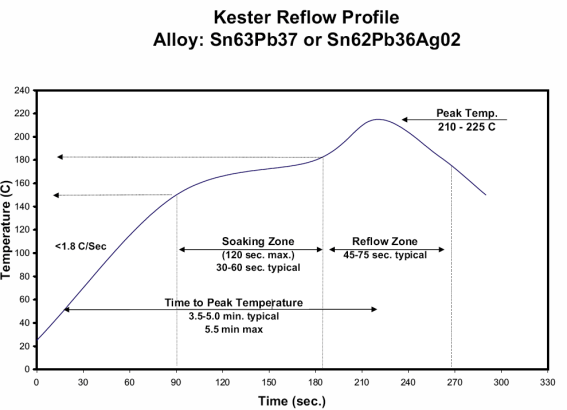
The actual time and temperature requirements is dependent on the type of solder paste used. I use Kester Sn63/Pb37 (tin/lead) solder paster. The recommended reflow profile is below:
In general, solder pastes can be divided into two groups based on the composition of the solder. Most lead based solder pastes consist of an allow of tin (Sn) and lead (Pb). This composition has a melting point of 183°C.
Lead-free pastes usually consist of a tin (Sn), silver (Ag) and copper (Cu) alloy. Lead-free solder paste begins to melt around 217°C with a maximum reflow temperature of 240°C. Current Restriction of Hazardous Substances (RoHS) regulations require consumer electronics to contain lead-free solder (some exceptions apply).
One of the first questions that one may ask when considering the stages of the reflow process is how to go about implementing it. The simplest approach is to apply heat if the temperature is below the set point and turn off heating if the temperature is above the set point. This method of control is known as OFF-ON control or more simply as ‘Bang-Bang Control‘. The problem with an OFF-ON control scheme is the temperature tends to over and undershoot the set point. This happens because the action-reaction of the reflow oven is not fast enough to regulate the temperature to maintain a constant set point. When the heating elements are turned off they do not immediately stop radiating heat. The internal temperature of the heating elements is higher than the temperature of the surrounding air so, thermal energy continues to transfer until they both are the same. When the temperature drops below the set point, the heating elements turn on but, it takes time for them to become hot enough to raise the temperature back to the set point. Thus, the temperature continues to drop until enough heat is applied to bring it back to the set point. A common way to deal with the issues of OFF-ON control is to use a PID routine which is the topic of our next discussion.
What is PID?
PID stands for “Proportional, Integral and Derivative.” Together, these three terms describe the basic elements of a PID controller. A PID controller is a type of control loop feedback system that calculates the difference between a measured input variable and a desired set point and attempts to minimize the error (how far are we away from set point) by adjusting the systems output. The output in our application is a heater control that varies the ON and OFF time in order to maintain a desired temperature.
What is Proportional Control?
The proportional term adds or subtracts output proportional to the current error value of the control system in order to drive the system back to the desired output (set point). The error value is given by how far the input (measured value) is away from the set point.
The proportional term is given by the following:
pTerm = Kp * error(t)
Where
Kp – A constant used to adjust the proportional response
error – Value given by subtracting the set point from the input (error = set point – input)
t – The time over which the input is sampled (sample time = 1 second for this explanation)
To summarize the proportional term:
- Error must exist in the system in order to have proportional drive.
- The system will try to correct the error by turning the heating elements ‘ON’ or ‘OFF’ in order to add or remove heat from the system.
- If the measured value is below the set point, heat will be added. If the measured value is above the set point, heat will be removed. If the measured value equals the set point, there is no error and thus, no proportional drive.
What is Integral Control?
A proportional only system would not be sufficient enough in our application to eliminate the error. Our system must be able to change its output according to the current error as well as past errors. The integral is proportional to both the magnitude (amount) of the error and the duration of the error. In other words, the integral is the sum of errors over time. This means the integral adds the amount of error as time passes and attempts to rapidly change the output to eliminate the error.
The integral term is given by the following:
iTerm = iTerm + (Ki * error)
Where
Ki – A constant used to adjust the integral response
error – Value given by subtracting the set point from the input (error = set point – input)
The integral component tracks accumulated error and attempts to accelerate the process towards the set point. This can cause the process to overshoot the set point if not kept in check. The integral component is kept in check in our application by clamping its output between a minimum and maximum value. The clamping routine is given by the following:
IF (iterm > outMax) THEN iTerm = outMax
IF (iTerm < outMin) THEN iTerm = outMin
Where
iTerm – Integral component
outMax – Maximum value the iterm can be
outMin – Minimum value the iTerm can be
To summarize the integral term:
- Error must exist in the system in order to have integral drive.
- The amount of error in the system is accumulated over time. Thus, a small error can become a large correction the longer error exists.
- The system is forced to correct the accumulated error.
- The effect from the integral component will cause the system to overshoot the set point as it attempts to reduce the accumulated error in the system if not limited.
What is Derivative Control?
The derivative term measures how quickly error changes with respect to time and affects the rate of change of the controller output. The rate of change is equivalent to measuring the slope of a line. The derivative term will attempt to reduce the magnitude of the overshoot that tends to be produced by the integral component.
The derivative term is given by the following:
dTerm = (currentTemperature – lastTemperature) * Kd
Where
currentTemperature – Current measured value
lastTemperature – Previous measured value
Kd – A constant used to adjust the derivative response
The derivative component must keep track of the previous measured value. This is accomplished by the following:
lastTemperature = currentTemperature
To summarize the derivative term:
- The system must be taking action. In other words, heat must be added or removed from the system over a period of time.
- The effect of the derivative component is based on how fast the system is heating up or cooling down within the sample period of once per second and is used to counter the overshoot produced by the integral component.
Output Drive…All Together Now!
Each of the PID components are calculated independently and added together to form the output drive. Take note that the dTerm is subtracted from the sum of the pTerm and iterm because the dTerm is derived from the measured input value(s). The output drive is what controls the process of determining how long to turn the system ON and OFF.
The output drive is given by the following:
Output = (pTerm + (iTerm – dTerm)))
Where
Output – Drive value for system control
pTerm – Proportional component
iTerm – Integral component
dTerm – Derivative component
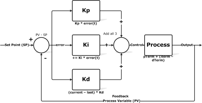
The output drive process is visualized in the below flowchart:
The above flowchart is a simplistic view of the temperature control process. The process begins by establishing a set point. The next step in the loop is to take a temperature reading. That temperature reading is used to calculate the error or how far we are away from the set point. Next, we calculate the Proportional, Integral and Derivative components and use those values to determine how much adjustment needs to be applied to regulate the system. In the case of our reflow oven, the amount of drive is determined by how long the heating elements are ON or OFF. This type of control can be considered a different take on the PID algorithm and is know as Time Proportional Control (TPC).
Time Proportional Control
Time Proportional Control, a form of Pulse Width Modulation (PWM), is a mathematical technique that allows a feedback controller to use an ON-OFF discrete actuator, such as a relay or Solid State Relay (SSR), as if it were a continuous actuator cable of generating control efforts anywhere between 0 and 100%. The concept of TPC is to turn the actuator ON and OFF for periods proportional to the desired control effort.
Our routine is given by:
timeOn = (tCycle * Output)/100
Where
timeOn – Value indicating how long power will be applied to the heating elements
tCycle – Time span for process
Output – Calculated value from the PID routine
The routine needs to keep track of how much time has elapsed in order to stay within the set process time span. This is accomplished by the following:
Tvar = Tvar + 1
IF (Tvar >= outMax) THEN Tvar = outMin
Where
Tvar – Variable used to track how much time has elapsed
outMax – Maximum value Tvar can be
outMin – Minimum value Tvar can be
The minimum and maximum time span for our application is 0 and 10 seconds, respectively. The above routine ensures the process time span does not go below or exceed the set time span.
I’ll go into a little more detail of TPC when I provide a brief overview of the code. For now, let’s move along to the controller circuit.
Controller Circuit
We will break the explanation of the controller circuit up into two parts. The first section will be the controller circuit and the second will be the AC control wiring.
Controller:
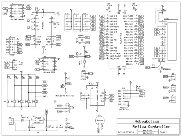
The controller circuit is a relatively simple design however, it has some extras that may come in handy for future expansion. The circuit is built around either a PIC16F877A or a PIC16F887. Both devices are pin compatible and have 14K of program memory, 368 bytes of ram, 2 PWM channels and 256 bytes of EEPROM. Microchip recommends using the PIC16F887 for newer designs. I chose the 16F887A for this project as I have plenty of them available. Check out the comparison and data sheet of the two devices here.
The circuit makes use of a MAX6675 Thermocouple IC (explanation here), a MAX3232 for programming and serial communication, a header for a Sparkfun FTDI Basic 5V USB breakout board for programming and serial communication, a 4×20 HD44780 Parallel LCD with PWM brightness control, a buzzer for audio feedback and a connection for a Adafruit DS1307 Real Time Clock (RTC). In addition, there are connections to control 3 relays or SSRs, outputs for 3 LEDs to coincide with the 3 relay/SSR outputs (LED outputs can be used to expand relay/SSR outputs), 5 menu switches, an on board reset switch, a off-board reset switch header and a connection for a manual/PC software control switch. The rest of the outputs that are not assigned to control functions are broken out to headers.
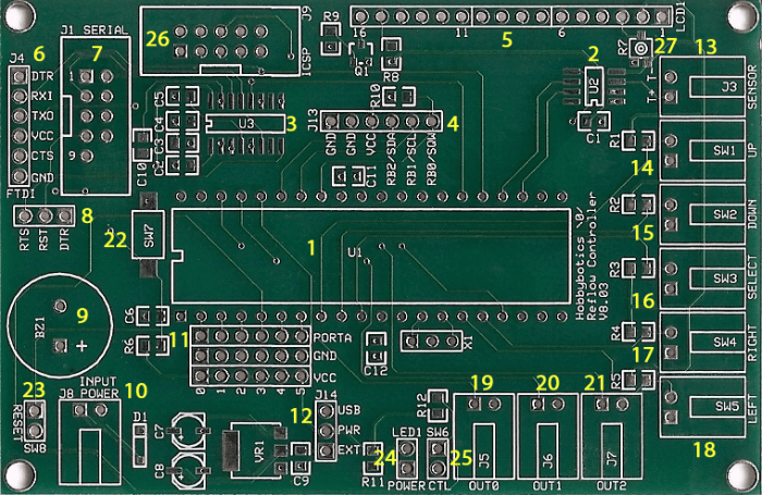
Here is a description of the main components and features:
| Item | Function |
| 1 | PIC16F877A or PIC16F887 microcontroller |
| 2 | MAX6675 Thermocouple Interface IC |
| 3 | MAX3232 serial IC |
| 4 | DS1307 RTC breakout header |
| 5 | 4×20 LCD header |
| 6 | FTDI Basic 5V USB header |
| 7 | DB9 serial port connector |
| 8 | Reset on RTS or DTR jumper. Used for updating firmware via serial or USB port |
| 9 | Buzzer |
| 10 | Input power |
| 11 | Additional I/O port breakout |
| 12 | USB/External power jumper |
| 13 | Type-K Thermocouple sensor |
| 14 | Menu switch (Up Arrow) |
| 15 | Menu switch (Down Arrow) |
| 16 | Menu switch (Select) |
| 17 | Menu switch (Right Arrow) |
| 18 | Menu switch (Left Arrow) |
| 19 | Relay/SSR output 0 |
| 20 | Relay/SSR output 1 |
| 21 | Relay/SSR output 2 |
| 22 | On-board reset switch |
| 23 | External reset switch |
| 24 | External power LED |
| 25 | External Manual/PC software control switch |
| 26 | In Circuit Serial Programming (ICSP). Upload new firmware with Melabs PIC Programmer |
| 27 | Contrast adjust potentiometer |
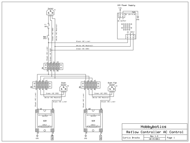
AC Wiring: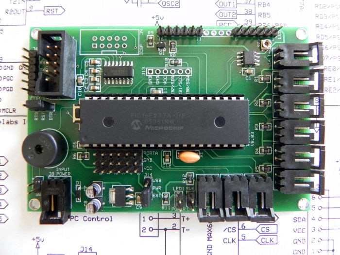 Here is a picture of the populated board:
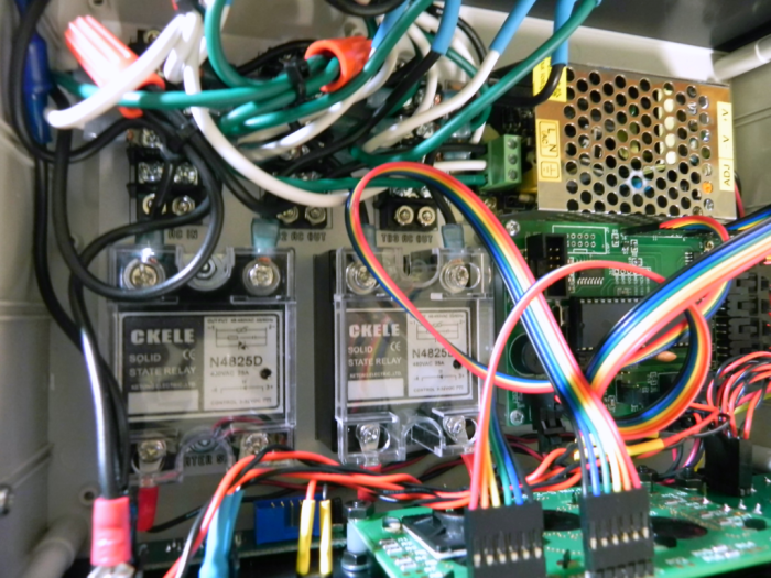
For this project, I used two of the outputs to control two SSRs. The first SSR controls the heating elements and the second controls the oven fan. Instead of building a power supply onto the board which, would have increased the overall size, I opted to use an external 120VAC to 12VDC power supply I found on Ebay for a good price.
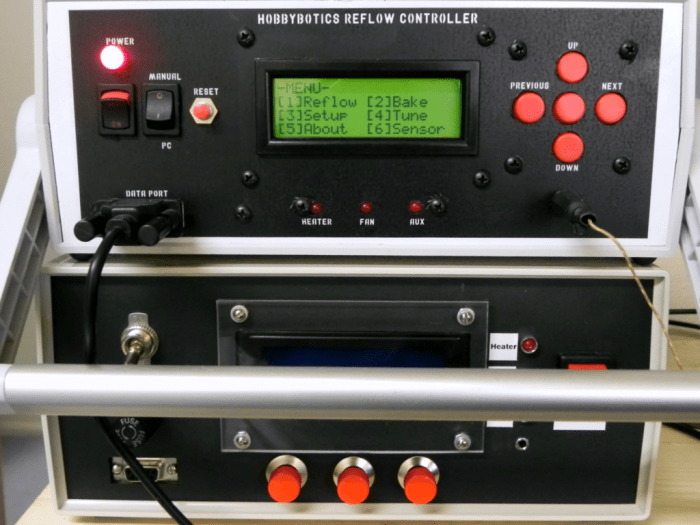
Here are some pictures of my setup:
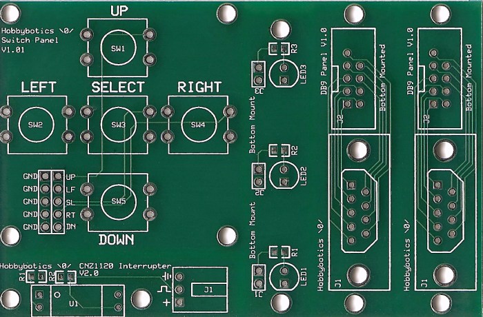
Here is a picture of the button, LED and DB9 PCB panels I designed for the above case. I placed all of the designs on the same PCB and cut them out with a circuit board shear. This was cheaper than ordering the boards as separate designs.
Toaster Oven Modification:
The layout of this project was chosen to allow the toaster oven to be used for reflow soldering without modification (if one chooses). This may be accomplished by following the AC wiring diagram presented earlier which will allow one to plug the toaster oven into a AC outlet that is controlled by the SSR. The controller/firmware will switch ON-OFF the oven to regulate heating and cooling.
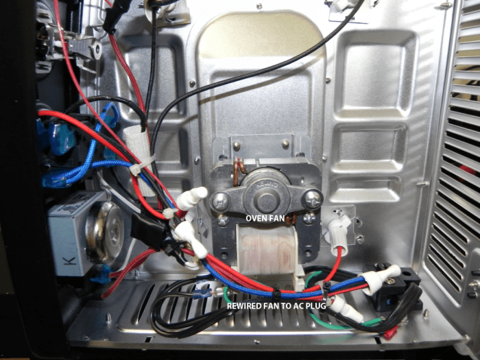
I needed to modify the oven I selected as it has an internal fan that helps circulate air. I wanted the fan to stay on the entire reflow cycle. One of the problems I ran into earlier on in the design is the temperature within the oven would dip whenever the fan was cycled off and on. Having the fan constantly circulating air prevented the temperature from dipping whenever the oven was turned back on.
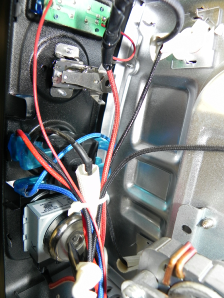
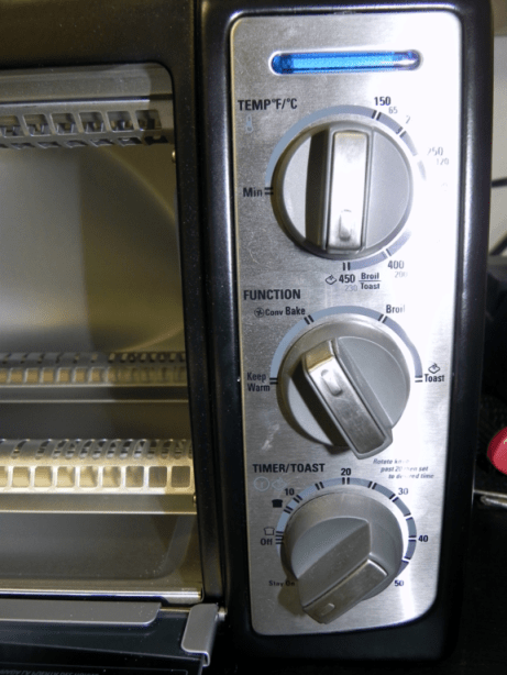
The toaster oven I selected is a Black & Decker Toast-R-Oven model TR04075BDC. Some pictures of the oven/modifications are below:
Documentation
- Schematic – PDF
- PCB – PDF
- Schematic – SCH
- PCB – PCB
- Mechanical Drawing – DXF
- Bill of Materials – TXT
- Firmware (Listing) – PDF
- Firmware(Pic Basic Pro V2.60) – ZIP
- Windows Application (C#) – ZIP
- DB9 Panel Files – link
- LED Panel Files – link
- Switch Panel Files – link
The schematic and PCB was developed with the freely available ExpressPCB software.
The project files and future updates can be found on my github page.
Build It
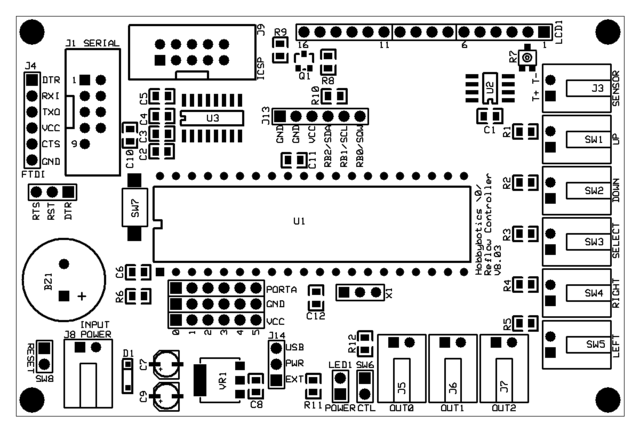
Reference the B.O.M above for a list of the parts necessary to complete the Hobbybotics Reflow Controller V8.03 board.
Reference the below layout file for component locations.
Firmware
The firmware for this project was developed using PicBasic Pro V2.60 from microEngineering Labs. You will need to download two libraries and place them into the PBP folder. The first library, DT_INTS-14, is an archive that contains the files DT_INTS-14.bas and ReEnterPBP.bas. The second library file is Elapsed_INT.bas. All of the files can be downloaded as part of the firmware archive I provide but, any updates to the author’s files can be found on his site here. The library files make it easier to use interrupts without having to resort to PicBasic interrupts, which has some overhead, or assembler interrupts. The Elapsed_INT file implements an elapsed timer using the instant interrupts library. A more in depth explanation can be found here.
Code Snippets:
I won’t rehash all of the code here as you can view the complete source for that but, I do want to point out some of the key routines.
Read Temperature:
The following procedure gets BUFFERSIZE temperature readings from the MAX6675, averages the values and returns the result:
| '------------------------------------------------------------------------------- | |
| ' Read temperature | |
| '------------------------------------------------------------------------------- | |
| READ_TEMPERATURE: | |
| 'Get a sampling of temperature values and write to temperature array | |
| FOR index = 0 TO BUFFERSIZE - 1 | |
| LOW CS | |
| SHIFTIN DAT, CLK, 0,[curTemp\16] | |
| HIGH CS | |
| ARRAY_TEMPS[index] = curTemp>>5 | |
| PAUSE 179 | |
| NEXT index | |
| curTemp = 0 | |
| 'Add up all the values in the array | |
| FOR index = 0 TO BUFFERSIZE - 1 | |
| curTemp = curTemp + ARRAY_TEMPS[index] | |
| NEXT index | |
| 'Take an average of the temperature values | |
| curTemp = curTemp/BUFFERSIZE | |
| RETURN |
The first FOR..NEXT loop takes x number of samples from the MAX6675 sensor and stores them in an array named ARRAY_TEMPS. The next FOR..NEXT loop cycles through the array and adds all of the values. Finally, an average of the sampled temperatures are taken and the result stored in a variable. The purpose of this routine is to smooth out the temperature measurements before using them in the PID routine.
The following procedures are responsible for processing each phase and computing the PID output. There’s also an intermediate step between the preheat and reflow phases that is used to ramp up the heat to the next set point.
| '------------------------------------------------------------------------------- | |
| ' Regulates heater controls based on phase temperature parameters | |
| '------------------------------------------------------------------------------- | |
| PROCESS_PHASE: | |
| GOSUB READ_TEMPERATURE | |
| GOSUB COMPUTE_PID | |
| WHILE (elapsedTime <> 0) | |
| IF (SecondsChanged = 1) THEN | |
| elapsedTime = elapsedTime - 1 | |
| GOSUB READ_TEMPERATURE | |
| GOSUB COMPUTE_PID | |
| TimeOn = (cycleTime * OutVal)/100 | |
| Tvar = Tvar + 1 | |
| IF (Tvar >= outMax) THEN Tvar = outMin | |
| IF (Tvar < TimeOn AND curTemp < setpoint) THEN | |
| PORTPIN = 1 : PINSTATE = 1 : GOSUB SET_PIN | |
| ELSE | |
| PORTPIN = 1 : PINSTATE = 0 : GOSUB SET_PIN | |
| ENDIF | |
| GOSUB DISPLAY_STATUS | |
| SecondsChanged = 0 | |
| ENDIF | |
| WEND | |
| RETURN | |
| '------------------------------------------------------------------------------- | |
| ' Computes the output drive from the individual PID components. | |
| '------------------------------------------------------------------------------- | |
| COMPUTE_PID: | |
| errorCurrent = setpoint - curTemp | |
| pTerm = Kp * errorCurrent | |
| iTerm = iTerm + (Ki * errorCurrent) | |
| IF (iterm > outMax) THEN iTerm = outMax | |
| IF (iTerm < outMin) THEN iTerm = outMin | |
| dTerm = (curTemp - lastMeasured) | |
| OutVal = (pTerm + (iTerm - (Kd * dTerm))) | |
| lastMeasured = curTemp | |
| RETURN |
The PROCESS_PHASE procedure begins by taking a temperature reading and computing the PID output. The WHILE..WEND loop cycles through the get temperature and compute PID process every second for the selected profile time constraints. For example, the soak phase has a default time requirement of 80 seconds thus, the while loop will continue to sample the temperature, compute the PID and turn the oven ON..OFF until the elapsedTime variable reaches 0.
The RAMP_UP procedure has no time requirement and simply ramps the temperature up to the required set point for the associated phase.
| '------------------------------------------------------------------------------- | |
| ' Ramps up to setpoint | |
| '------------------------------------------------------------------------------- | |
| RAMP_UP: | |
| GOSUB StartTimer | |
| WHILE (curTemp < setpoint) | |
| IF (SecondsChanged = 1) THEN | |
| GOSUB READ_TEMPERATURE | |
| GOSUB COMPUTE_PID | |
| TimeOn = (cycleTime * OutVal)/100 | |
| Tvar = Tvar + 1 | |
| IF (Tvar >= outMax) THEN Tvar = outMin | |
| IF (Tvar < TimeOn) THEN | |
| PORTPIN = 1 : PINSTATE = 1 : GOSUB SET_PIN | |
| ELSE | |
| PORTPIN = 1 : PINSTATE = 0 : GOSUB SET_PIN | |
| ENDIF | |
| GOSUB DISPLAY_STATUS | |
| SecondsChanged = 0 | |
| ENDIF | |
| WEND | |
| RETURN |
The RAMP_UP procedure begins by starting the timer interrupt which cycles once per second. The WHILE..WEND loop simply takes a temperature reading every second, computes the PID and turns the oven ON..OFF until the associated phase set point is reached. The interrupt timer is reset once the loop completes.
The final procedure I want to cover is the Instant Interrupts timer I introduced earlier. This procedure and associated library makes it simpler to implement an assembler timer without having to hand code a routine.
| '------------------------------------------------------------------------------- | |
| ' Instant Interrupts Elapsed Timer routine | |
| '------------------------------------------------------------------------------- | |
| ASM | |
| INT_LIST macro ;IntSource, Label, Type, ResetFlag? | |
| INT_Handler TMR1_INT, _ClockCount, PBP, yes | |
| endm | |
| ;Creates the interrupt processor | |
| INT_CREATE | |
| ;Enable Timer 1 Interrupts | |
| INT_ENABLE TMR1_INT | |
| ENDASM | |
| 'Reset Time to 0d-00:00:00.00 | |
| Gosub ResetTime |
This routine along with the Instant Interrupts include files allow us to implement a pretty accurate elapsed timer routine without having to use the PicBasic Pro ON INTERRUPT routine. Some of the benefits are not having to wait for other programming statements to execute before the interrupt routine gets serviced, not having to memorize or set interrupt enable bits/flags and the code size is minimized. More details can be found here and here.
Built into the firmware is the capability to operate the controller in manual or computer control. The manual/PC mode is set by a toggle switch. On start up, the firmware checks this switch and branches accordingly. Either mode can be exited by pressing the reset switch on the front panel or by setting the mode switch and turning OFF..ON the power switch.
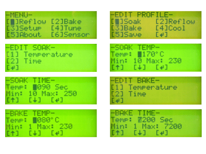
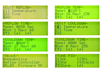
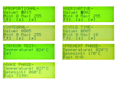
Below are screen shots of the 4×20 LCD with the controller in manual mode:
That wraps up the overview of the firmware so, let’s move along to the optional Windows control application.
Software
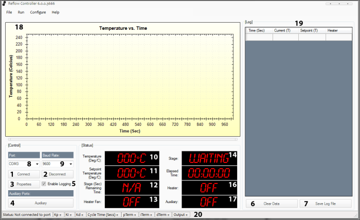
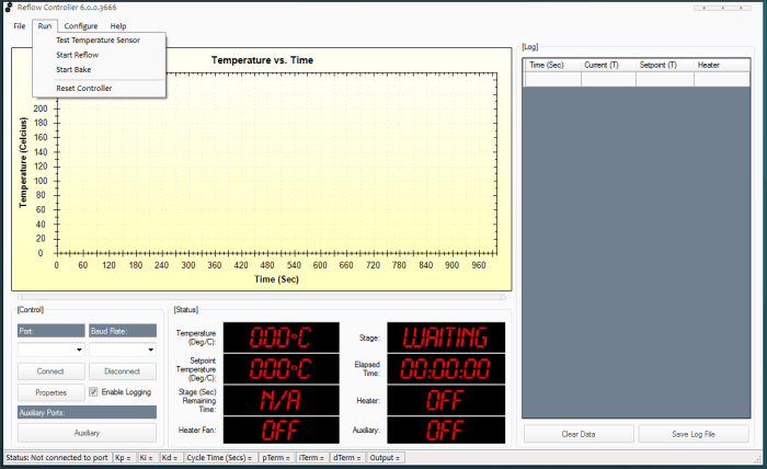
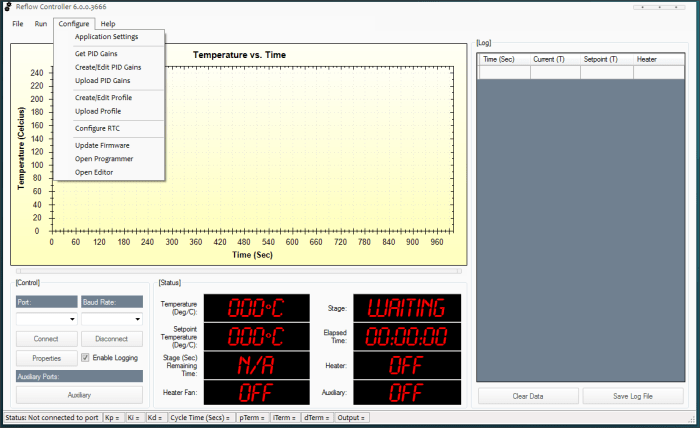
The windows application I developed for this project allows full control over the controller with the added benefit of being able to graph/save data, upload new firmware (PicBasic Pro required), create/modify reflow profiles and export data to a *.csv file for import into Excel. This application was developed with C# 2010.
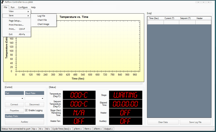
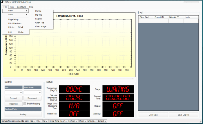
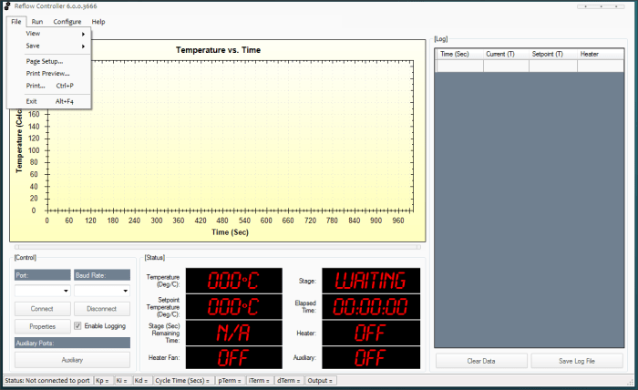
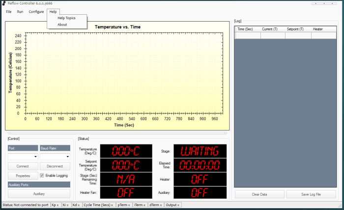
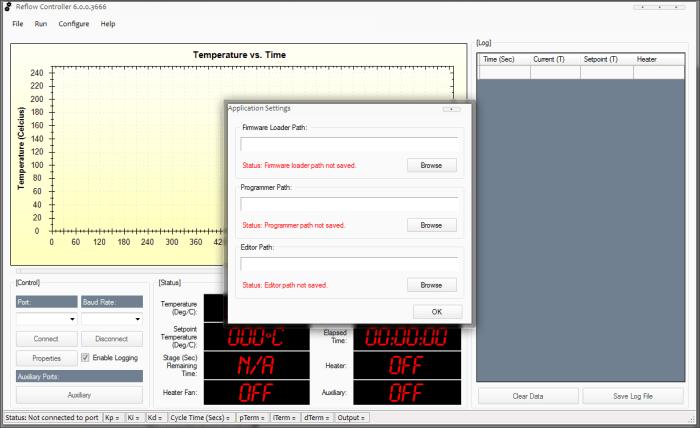
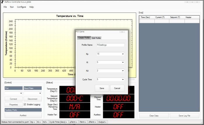
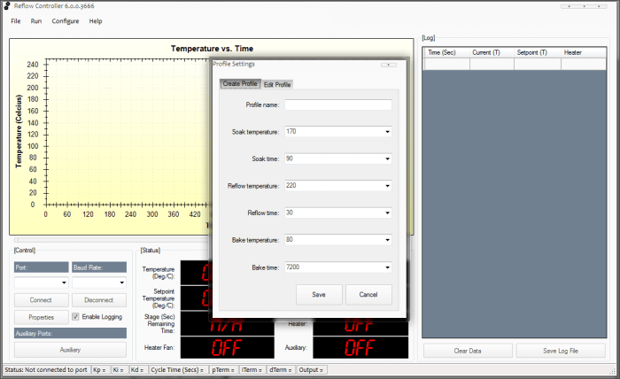
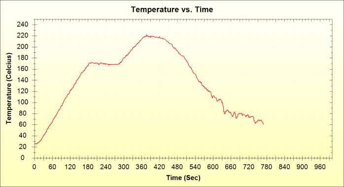
Here are some screen captures of the application:
| Number | Description | Control Function |
| 1 | Connect Button | Establishes a serial connection. |
| 2 | Disconnect Button | Disconnects serial connection. |
| 3 | Properties Button | Opens device manager applet so that serial port properties can be viewed or edited. |
| 4 | Auxiliary Button | Connects or disconnects the device attached to the auxiliary jack. |
| 5 | Enable Logging Checkbox | Enables or disables data logging. |
| 6 | Clear Data button | Clears data grid. |
| 7 | Save Log File button | Save data to a log file that is compatible with any spreadsheet or text editor software. |
| 8 | Port Selection | This field is loaded with detected serial ports and allows a port to be selected. |
| 9 | Baud Rate Selection | This field is loaded with available baud rates. The default baud rate is 9600. |
| 10 | Temperature Label | Displays current oven temperature. |
| 11 | Set Point Temperature label | Displays current set point temperature. |
| 12 | Stage Remaining Time label | Displays the remaining time for each temperature stage. |
| 13 | Heater Fan label | Displays ON/OFF state of oven fan. |
| 14 | Stage label | Displays the current temperature stage. |
| 15 | Elapsed Time label | Displays total time the process is taking. |
| 16 | Heater label | Displays ON/OFF state of heater elements. |
| 17 | Auxiliary label | Displays ON..OFF state of oven heaters. |
| 18 | Log Data Chart | Graphical chart that plots the time (seconds) and temperature (Celsius) of the reflow process as a line graph. |
| 19 | Log Data grid | Captures the time (seconds), temperature (Celsius), set point (Celsius) and heater ON/OFF state. |
| 20 | PID status label | Displays port status and information about current PID settings. |
From the “Run” menu, there are options to test the thermocouple sensor or start a reflow/bake session using a profile that has been uploaded to the controller. The bake option is used to dry moisture sensitive components prior to reflow soldering.
The “Application Settings” menu option allows a default application to be defined for firmware (Microcode Loader), a default application for the firmware loader (MeLabs Programmer) and a default editor (PicBasic Pro). These file paths are used to upload firmware from within the Reflow Controller application.
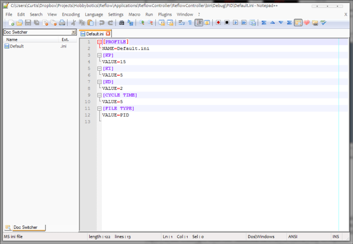
The “Create/Edit PID Gains” menu option allows separate PID gains to be created and/or edited.
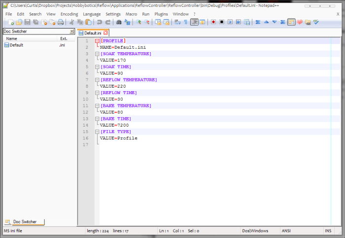
The “Create/Edit Profile” menu option allows separate reflow profiles to be created and/or edited.
The reflow and PID profile settings are saved to *.ini files. Here are some screen shots of typical file contents:
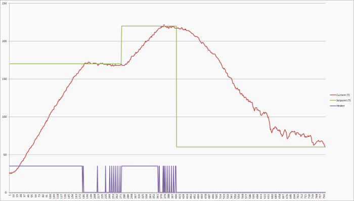
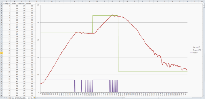
Here are some screen shots of a reflow chart created with data imported into Excel:
One of the key features of the application is the ability to save and restore the last connected serial port and associated settings. The application will detect all serial ports on the system and populate them in the ‘Port’ combo box. An error will be raised if a connection is attempted with a port that is already in use.
There is a lot of built in functionality that I have not covered and even though the application is robust, it is still in development. I will post future updates to my github page.
Conclusion
This project covered my design for a reflow controller based on a common toaster oven that is more cost effective for the hobbyist than purchasing a commercial version. We began by discussing some of the advantages to using SMD components over through-hole components. Next, a brief explanation of the crucial phases of the reflow process was presented along with typical temperature profiles for each stage. Third, we went over the basics of Proportional, Integral and Derivative control, commonly referred to as PID, and how each component was implemented in the firmware. Finally, we built the project, reviewed key points of the firmware, and presented the optional windows application. Armed with the information presented in this project, one should be able to implement a cost effective reflow controller based on a toaster oven and move into the realm of smaller SMD components.
Related Links
Hobbybotics Reflow Oven Controller V8.03 Gallery
Sparkfun Surface Mount Soldering Tutorials
References
- [1] Goossens, Paul. “Reflow Solder Controller: Soldering SMDs in an ordinary electric oven.” Elektor Magazine December 2007: 16-19.
Disclaimer
This example shows hardware and software used to implement the design. It is recommended the viewer use sound judgment in determining and/or implementing this example for any particular application. This example may include information from 3rd parties and/or information which may require further licensing or otherwise. Additional hardware or software may be required. Hobbybotics or any affiliates does not support or warrant this information for any purpose other than a design example and takes no responsibility for any mishaps (none being implied).





Is it possible to modify that controller and sofware to operate with BGA rework station? The problem is that rework station requires two thermocouples, two outputs to drive SSR for top and bottom heater. That could be nice to see second graph time vs temp for second thermocouple.
It should be possible to achieve what you are looking for by building the MAX6675 Thermocouple Breakout board I presented in the projects section. You can connect that board to some of the spare I/O pin headers. You’ll need to modify the firmware to run simultaneous PID loops. The chart control in the accompanied software can be modified to display as many graphs you like. Maybe this will be my next modification to the controller as I port it away from ExpressPCB. Hope this answers your question. Keep a lookout for a revamp to this board and software.
[…] project may take the cake on high-end reflow retrofits. It’s a HUGE project which uses a toaster oven to reflow surface mount circuit boards. And the fact that it bursts with features makes us […]
Looks to me like a great product. Have you considered either doing that yourself or arranging for someone else to sell it?
I am considering offering this as a kit/product. I want to do a little refining first to add a little extra finish. I am working on some really good upgrades and features. For instance, the front panel is made up of separate boards which is a little more difficult than it needs to be. The design could benefit by placing the LCD, buttons and communication panels on one PCB. That would mean only one cable that plugs into the controller board. I have been working on a re-design that pulls all of this together. I’ll offer a finished product at that time and keep the design files open.
Awesome project and a very clear explanation of PID control as a bonus. Thank you for publishing this 🙂
Hi, I would be interested in purchasing this as a kit if it were offered. Please contact me by email if you are interested.
Best regards
[…] to, since you might need additional parts such as resistors, wiring, or a custom PCB.Useful LinksHobbybotics Reflow Controller V8.0Laser-Cut Mylar SMT StencilHack a Toaster Oven for Reflow SolderingDIY Lab Equipment: Build Your Own […]
[…] There is plenty of information on the internet on such conversions: here is one example, a second, a third, a fourth; there are surely many […]
Hi im currently makeing a rework station /reball machine would love to chat with you about planning detail and what not this guide has helped me alot and want to port it to an ardrino interface shoot me an email light0070702@gmail.com
Reply to this post and maybe I can provide some guidance that others could also benefit from
[…] are many hobbyists out there who made their own reflow soldering machine, like this guy, or that guy, or this dude, that pal etc. It made me realize that if you want to be somebody in electronics you […]
Can you expound on the rewiring of the fan? I can’t see where the change is(eyesight problem). I assume you left the control panel as is and are just running at high without the mechanical timer? This seems a lot safer than totally rewiring like I’ve seen in others…
To help circulate air in the oven to evenly distribute the heat, I wired the fan to the second SSR so that I can turn it ON/OFF separately from the oven. The original wiring would mean the fan would turn ON/OFF whenever the oven was turned ON/OFF. All I did was wire the SSR in series with the LINE side of the fan. Hope this helps.
Curtis
Just for the information of anyone desiring to build this project. I think that it is a great project! Thanks. But the assertion that the hex code will work with the PIC16F887 chip is not true. The code will not work on the 887. I have tried my best to get it to work on the 887 but it will not. I suspect that it is a problem with the interrupts but I have not tried to look at the code. It does work just fine on the 16F877A chip which, fortunately, is still available.
Steve
Steve,
You are correct, the hex file was compiled for the 887A. The source code is available for those that want to compile it for the 887. I’ll dig up the files and add a hex file for the 887.
Thanks for pointing that out.
Curtis
I Seem it is a very beautiful project. I would like to realize. But i understand hardware and firmware enough. In software i am not so much able. Please explain to me how trasform the Reflow controller application in an executable windows application. Thanks a lot
If you are talking about the windows application then, you need to download the free version of Visual Studio from Microsoft. Open the application using C# and compile it.
In your TRANSMIT code I find that some WORDS like “curTemp” are transmitted as a BYTE. Because of transmitting BYTES I understand the the separation of elapsedTime into HIBYTE and LOWBYTE . Is there and oversight on my part?
Jan,
You are correct, curTemp is a byte variable. PicBasic Pro splits a word variable into two bytes (hi byte and low byte) to transmit over the serial port.
Hi
Is there any way to use this windows application for other projects at least the plotting would be nice
You can, but you’ll need to look at the code to see how the serial commands are formatted. Instead, you might want to check out Serial Studio https://github.com/Serial-Studio/Serial-Studio. Serial Studio is more generic and easier to set up than my application which was pretty specific to this project.