Introduction
I designed a breakout board for the Analog Devices AD595-AQ Cold-Junction Compensated Type-K Thermocouple interface. This breakout board is an alternative to the MAX6675 breakout from a previous project. The difference is the AD595 can be operated from a single analog pin of a micro-controller. This project details a prototype and finished PCB design along with some sample Arduino sketches for demonstration.
The specifications for the AD595 are:
- Works with any Type-K Thermocouple
- Accuracy of +/- 3 degrees Celsius (AD595-AQ)
- Has a temperature range up to 500 degrees Celsius in 10 mV/C degree increments
- Operating voltage: +5V (see datasheet for dual supply operation)
- Single analog input (ADC)
A thermocouple is a device consisting of two different metal alloy conductors that produce a voltage that is proportional to a temperature difference between the joined end of the two conductors. Dissimilar metals are chosen to maintain a predictable and repeatable temperature range profile.
Basically, two different metals are chosen in order to be able to measure a certain temperature range with an emphasis on stability. These two metals are joined together at one end and when the junction is heated or cooled a small voltage is produced that can be correlated back to a temperature value.
Thermocouples are available in many different types of metals and/or calibrations with the most common being of type J, K, T and E. Each calibration has a different temperature range but, the maximum range varies with the diameter of the wire used to create the thermocouple. Refer to the following document for temperature limits based on wire size (Thermocouple Reference Guide).
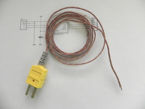
Below is a picture of a Type-K Thermocouple:
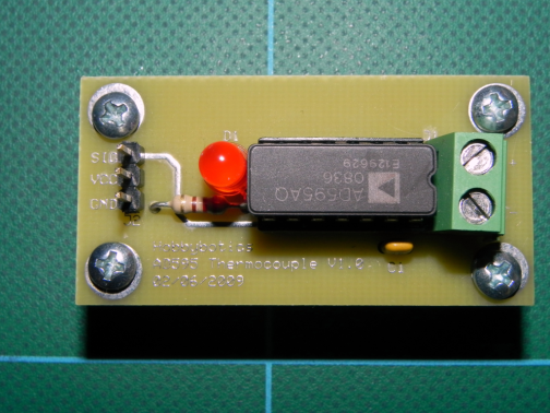
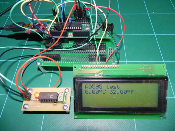
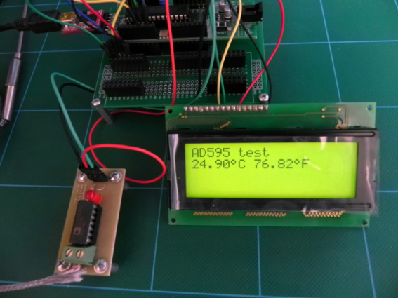
Here are some pictures of the prototype breakout board:
The AD595 as used in this project is designed to work with a Type-K Thermocouple which is made up of chromel (90% nickel and 10% chromium) and alumel (95% nickel, 2% manganese, 2% aluminum and 1% silicon).
Common uses are in HVAC systems, kilns and heating controllers.
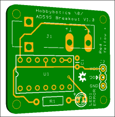
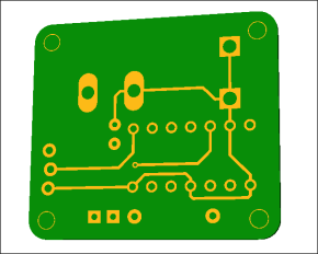
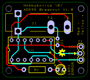
The breakout board in the above pictures is a prototype design. The finished PCB is visualized in the below pictures:
Documentation
- Schematic – PDF
- PCB – PDF
- Board Files – PRJ
- Manufacturing Files – GBR
- Bill of Materials (With Data Sheets) – ZIP
- Bill of Materials – PDF
- AD595 Datasheet – PDF
The board files was developed with the freely available DesignSpark PCB.
Files and updates are available on the associated github page.
Build It
Reference the B.O.M above for a list of the parts necessary to complete the Hobbybotics MAX6675 Breakout.
Reference the below schematic and layout file for component locations.
Use It
I developed a couple of Arduino libraries to support the AD595 breakout board. The files are available on the associated github page.
Files and updates are available on the associated github page.
| Pin | Function |
| VCC | +5V pin |
| DO | Signal pin. Outputs a voltage between 0 and 5V that correlates with the measured temperature. Can be connected to any of the analog pins (ADC). |
| GND | Ground pin |
The conversion formula is simple and probably looks familiar to some of you:
| /* | |
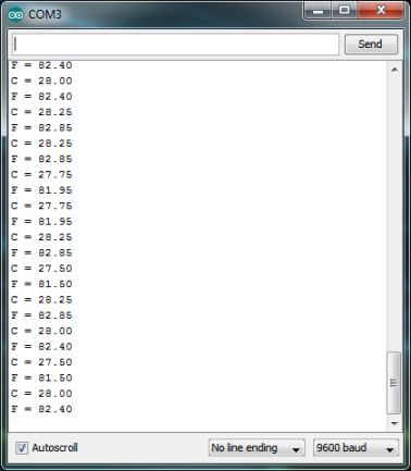
| Demonstration sketch for Hobbybotics AD595 Thermocouple breakout board. | |
| Reads temperature from AD595 in Celsius and Fahrenheit. Prints results to serial monitor. | |
| */ | |
| #include <AD595.h> | |
| AD595 thermocouple; | |
| void setup() { | |
| Serial.begin(9600); | |
| thermocouple.init(0); | |
| Serial.println("AD595 test"); | |
| // wait for AD595 chip to stabilize | |
| delay(500); | |
| } | |
| void loop() { | |
| // basic readout test, just print the current temp | |
| Serial.print("C = "); | |
| Serial.println(float(thermocouple.measure(TEMPC))); | |
| Serial.print("F = "); | |
| Serial.println(float(thermocouple.measure(TEMPF))); | |
| delay(1000); | |
| } |
| /* | |
| Demonstration sketch for Hobbybotics AD595 Thermocouple breakout board. | |
| Reads temperature from AD595 in Celsius and Fahrenheit. Prints results to I2C LCD. | |
| */ | |
| #include <AD595.h> | |
| #include <LCD.h> | |
| #include <Wire.h> | |
| AD595 thermocouple; | |
| // Default I2C address for LCD is 0. | |
| LCD lcd(0); | |
| // make a degree symbol | |
| uint8_t degree[8] = {140,146,146,140,128,128,128,128}; | |
| void setup() { | |
| lcd.begin(20, 4); | |
| lcd.createChar(0, degree); | |
| thermocouple.init(0); | |
| // wait for AD595 to stabilize | |
| delay(500); | |
| lcd.clear(); | |
| lcd.setCursor(0, 0); | |
| lcd.print("AD595 test"); | |
| } | |
| void loop() { | |
| float temp_c; | |
| float temp_f; | |
| // Read values from the sensor | |
| temp_c = thermocouple.measure(TEMPC); | |
| temp_f = thermocouple.measure(TEMPF); | |
| lcd.setCursor(0,1); | |
| lcd.print(temp_c); | |
| lcd.write((byte)0); | |
| lcd.print("C "); | |
| lcd.print(temp_f); | |
| lcd.write((byte)0); | |
| lcd.print('F'); | |
| delay(1000); | |
| } |
Related Links
Hobbybotics AD595 Thermocouple Breakout V1.0 Gallery
Omega Engineering Thermocouple Connectors
Disclaimer
This example shows hardware and software used to implement the design. It is recommended the viewer use sound judgment in determining and/or implementing this example for any particular application. This example may include information from 3rd parties and/or information which may require further licensing or otherwise. Additional hardware or software may be required. Hobbybotics or any affiliates does not support or warrant this information for any purpose other than a design example and takes no responsibility for any mishaps (none being implied).




Congratulations very usefull