Projects – Hobbybotics Reflow Controller Quad V1.0

Here’s a quick update to the new reflow controller project I introduced earlier.  I have fully populated one of the prototype boards and began to write test sketches to ensure it functions properly.  The project is moving a little slower right now as I am in the process of closing on a new house and that has been taking up a lot of my time.

2013-03-06 02.44.49_1024x768 2013-03-06 02.44.40_1024x768 2013-03-06 02.44.15_1024x768

The last picture shows an early prototype for the LCD/Button interface for the controller.  I am in the process of redesigning the LCD/Button interface to use a 4-way rotary navigation switch with a center select button.  I borrowed this idea from the Viki LCD project over on Kick Starter.  I’ll post more updates in the coming weeks.

Projects – Hobbybotics Reflow Controller Quad V1.0

I’ve been working on a redesign of the original reflow controller.  Here are the features for the new board:

  1. Four MAX31855 Type-K Thermocouple interfaces
  2. DS3234 Real Time Clock with battery backup
  3. FT231x USB
  4. XBee or Bluetooth Wireless
  5. MCP23008 I/O Expanders for 2-wire expanded communication
  6. ULN2803 Darlington buffered output relay/SSR control
  7. Internal or external micro SD interface
  8. External LCD I2C interface/input
  9. ATMega 1284P TQFP AVR with Arduino bootloader
  10. 16 MHz Crystal

Take a look at the new board:

2013-02-19 01.32.48_1024x768

2013-02-19 01.36.35_1024x768

download

 I’ll post more on this project in the coming days.  I’ll be offering this project as a full kit for those who are interested.

Projects – Hobbybotics Serial LCD Controller V3.0

p80900101Some of the projects I design make use of character displays. The Liquid Crystal Displays (LCD) I typically use are based on the Hitachi HD44780 LCD command set. Most HD44780 compatible LCDs use a standard 16 contact interface and are known as parallel devices. This project presents a design that allows the LCD to be controlled by a single serial pin from a microcontroller or a serial connection on a computer. Check out the project here

Projects – Crazy for 3D Printing – First 3D Design

In the first installment of my adventures with 3D printers I talked briefly about Cubify Invent from the makers of the Cube 3D printer.

For just $49 you can pick up Cubify Invent which has many features that are contained in more expensive 3D packages such as Solid Works.  The work flow is similar to 123D by AutoDesk (free software).  You start your design by drawing a sketch in a 2D plane and selecting extrude or many of the other tools to convert the drawing into a 3D representation.  There is a 15 day trial so you can test it out.

Cubify offers some basic video tutorials to get you started.  You can also checkout Cubify Fans blog for more in depth tutorials (my favorite).

As a personal rule-of-thumb, I typically give myself roughly 30 minutes to figure out the basics of new software without having to reference a manual.  I believe that basic user experience should become routine within the first 30 minutes of use with more time reserved for tutorials and manuals once I have buy-in.  I found Cubify Invent easy to understand and within a couple of hours I had enough knowledge to create my first design.

In the first installment I stated I was using my Replicator 3D printer to build a Ecksbot 3D printer. Since the introduction I have aligned the frame, installed the stepper motors and selected the control electronics.  I decided to go with the Ramps 1.4 electronics and power it all with a WW1230A 12VDC @ 30A switching power supply.  The Ramps electronics and power supply can be found for a great price on Ebay.

I decided to clean up the mounting scheme for the electronics during the initial phases of the Ecksbot build. I’m looking for portability so, I decided to mount the power supply onto the printer. I also wanted to add more protection against accidental contact with the AC wiring than what is afforded by the barrier strip cover. As such, I present a front cover, rear cover and mounting plate for the WW-1230A 12VDC 30A switching power supply.  The design was created with Cubify Invent and available here on Thingiverse.


Follow the below instructions if you want to duplicate this project:

I printed the design files on the MakerBot Replicator with the following settings:

Object Infill: 10%
Layer Height: 0.3
Number of Shells: 2
Feed Rate: 41
Travel Feed Rate: 56
Print Temperature: 230
Heat-Bed Temperature: 115

Print one of each:

WW-1230A Front Coverx2
WW-1230A Rear Coverx1
Mount Plate Leftx4
Mount Plate Rightx4
Mount Plate Centerx4

Print 4 mount brackets from thing:10621 – thingiverse.com/thing:10621

The mounting plate is made from three pieces:

left mount plate
right mount plate
center mount plate

Snap the three pieces together and use super glue or acetone/ABS glue to bond.

Use M4 x 16 mm bolts to secure mount plate to 3D printer frame.

I’m using the following components from Mouser Electronics:

Power Entry Module

SPST ON/OFF Rocker Switch

I’m using the following component from Ebay:

WW-1230A 12VDC 30A Switching Power Supply (search for 12V DC 30A 360W Regulated Switching Power Supply)

This wraps up the discussion of my first experience with using Cubify Invent.  Next time I’ll continue the Ecksbot build with a discussion of how I intend to mount the electronics along with what hot-end I chose and how I mounted it.

Projects – Crazy for 3D Printing – An Introduction

Back in June 2012 I posted about purchasing a Makerbot Replicator 3D printer with dual extruders. Since then, I have been working with it so much that I have neglected many of my other project(s). As such, I intend to document my journey into the world of 3D fabrication.

According to the RepRap wiki:

“RepRap is humanity’s first general-purpose self-replicating manufacturing machine.

RepRap takes the form of a free desktop 3D printer capable of printing plastic objects. Since many parts of RepRap are made from plastic and RepRap prints those parts, RepRap self-replicates by making a kit of itself – a kit that anyone can assemble given time and materials. It also means that – if you’ve got a RepRap – you can print lots of useful stuff, and you can print another RepRap for a friend

RepRap is about making self-replicating machines, and making them freely available for the benefit of everyone…”

The RepRap movement has spawned improvements and innovations that led to derivatives such as The PrintrbotFoldaRapRostock and Replicator.  These printers use a method known as extrusion or addictive layering in which material is placed onto a build platform a layer at a time.


One of the first actions I took after many laborious nights of tweaking, adjusting, test printing and more tweaking is heading over to Thingiverse and downloading some open source creations.

One of the first objects I built is a derivative (with some modifications) of the Original Eggbot by Evil Mad Scientist.

Here is the Original Eggbot:

Here is the printable version that is available on Thingiverse:

Here is my version of the printable Eggbot:

I added a modified endplate from here so that my pin attachment will have full range.

Naturally, after printing many designs from Thingiverse, I wanted to embrace the RepRap movement and print a 3D printer.  I scoured the RepRap wiki for ideas and settled on the Ecksbot printer which is a derivative of the Prusa Mendel.  Building your own 3D printer is not for the faint of heart but, the savings and knowledge gained is worth the journey.  The first issue I ran into is the Ecksbots files are designed to be printed on a larger build platform than what is available on the Replicator.  This posed a problem when I wanted to print the Y-Carriage.  A request made to the Ecksbot creators yielded a resized Y-Carriage that fit on the Replicator’s build platform.  If you plan to build your own and intend to use the Replicator to fabricate the parts, be sure to download the file labeled “Y_Cart_ReplicatorResize_x1.STL.”

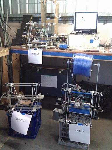
Here are some pictures of my mostly completed Ecksbot:

There are two software options supported by Makerbot for use on the Replicator and the recently released Replicator2.  The first being ReplicatorG and the second being MakerWare.

ReplicatorG focuses more on the Skeinforge slicing engine whereas MakerWare focuses more on the Miracle-Grue slicing engine in active development by MakerBot.

ReplicatorG:

MakerWare:

MakerWare is currently in beta but offers some welcomed capabilities that are missing from ReplicatorG.  My favorite is the ability to import multiple parts onto the build plate.  This allows one to easily combine prints into a single session.  Another favorite is the ability to run multiple slicing sessions at the same time.  Again, the software is in beta and lacks the capability to decipher between the difference in the build area size of the Replicator2 and the Replicator.  The way I get around this is to add parts to the build surface in MakerWare, save the session as an STL file and open in ReplicatorG.  Now I can adjust as necessary and print from ReplicatorG or MakerWare.

A natural progression after getting comfortable with a 3D printer is to design some objects.  There are a number of free offerings that can export to the STL format.  The STL file will be converted into g-c0de by the slicer application.  A couple of popular free applications is Sketchup and OpenSCAD.  Sketchup loosely follows the path of traditional 2D/3D CAD applications while OpenSCAD takes a programming language approach.

Sketchup:

OpenSCAD:

An online offering is Tinkercad:

For just $49 you can pick up Cubify Invent from the makers of the Cube 3D printer.  Cubify Invent has many features that are contained in more expensive 3D packages such as Solid Works.  The work flow is similar to 123D by AutoDesk (free software).  You start your design by drawing a sketch in a 2D plane and selecting extrude or many of the other tools to convert the drawing into a 3D representation.  There is a 15 day trial so you can test it out.

Cubify offers some basic video tutorials to get you started.  You can also checkout Cubify Fans blog for more in depth tutorials (my favorite).

This wraps up my introduction/experience in 3D printing.  I’ll continue this series with some projects that I am working on as I learn to use Cubify.  My initial designs are currently centered on modifying the Ecksbot 3D printer I presented above.  I’ll also dive deeper into the printable Eggbot I briefly discussed above.  Till next post, enjoy!

Project – Internet Enabled Multi-zone Thermostat (DesignSpark Challenge Entry)

I’m currently working on documenting this project but, here is a link to my entry for the DesignSpark Challenge. The competition has already been decided and my entry garnered an honorable mention award! This was the first competition that I entered and to win an honorable mention out of over 1000 entrants means a lot to me. I also won a Community Choice Award during the competition for the most popular project. I have to say this was a difficult competition as there was a lot of requirements. For instance, I had to learn how to use DesignSpark PCB as it was required to produce an extension board for the ChipKit Max32. I had to learn the ins and outs of the Max32 as it is/was not entirely compatible with all of the Arduino libraries. This meant some modifications to libaries in order to make them compatible with the Max32. Lastly, there was a long wait for the PCBs to be shipped from China which meant any mistakes in the board files meant lost development time (I made a few mistakes). Time management was definitely crucial in this competition and I ran all the way until the last few minutes for project completion trying to get everything together. A few mistakes kept me from adding all of the software features that I had intended but, I have pretty much completed them since the competition. Check out my entry here and be on the look out for full documentation on my blog to include some extension projects (There’s a lot of goodies in this design that can be carried over into other projects).

Projects – Hobbybotics Reflow Controller V8.03

A while ago I decided to start designing my circuits using Surface Mount Devices (SMD).  There are many advantages to using SMD components over through-hole components.  Some of the major advantages are size and cost.  The smaller size means I can make the circuit boards smaller.  In addition, smaller components and smaller circuit boards means lower costs.  One of the disadvantages to SMD components is they are more difficult to solder than through-hole components.  The solution is to use what is called a reflow oven.  The following project details how I designed and built a reflow controller based on a MAX6675 Thermocouple interface and use it to control a common toaster oven in order to reflow surface mount circuits.  Check out the project here.

Projects – Hobbybotics SHT1x Humidity/Temperature Breakout V1.0

I designed a breakout board for the Sensirion SHT1x Humidity and Temperature Sensors.  The SHT1x family of sensors can measure relative humidity, temperature Celsius and temperature Fahrenheit.  My plans are to use the design for various heating and control projects such as a wireless thermostat, greenhouse controller and some environmental projects.  The project link details a SHT15 but, any of the sensors that share a common footprint can be used with the breakout board.  I also developed (modified) an Arduino library for use with the Sensirion sensors.  Check out the project here.

Projects – Hobbybotics MAX6675 Thermocouple Breakout V1.0

I designed a breakout board for the MAX6675 Cold-Junction Compensated Type-K Thermocouple interface.  My plans are to use the design for various heating control projects such as a Sous-vide cooker, wireless thermostat, smoker controller, beer brew controller, reflow oven and some environmental projects.  Check it out here.