Build – Day 1
Build – Day 2
Build – Day 3
Build – Day 4
Build – Day 5
Related Links
— Day 1: 31 May 2012:
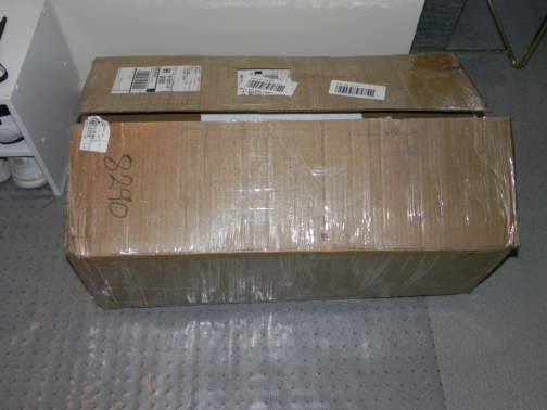
My FireBall V90 CNC machine arrived on 30 May 2012. The first order of business is to open and inspect the contents (This turned out to be a smart move). But first, I snapped a picture of the box exactly where the UPS guy left it. Of course I did not want to move it as the box weighed every bit of 80 pounds.
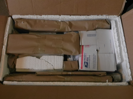
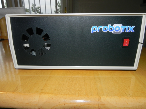
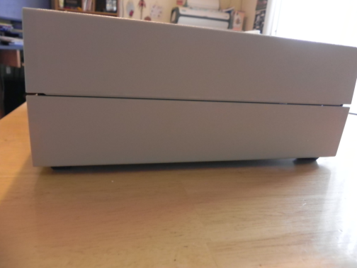
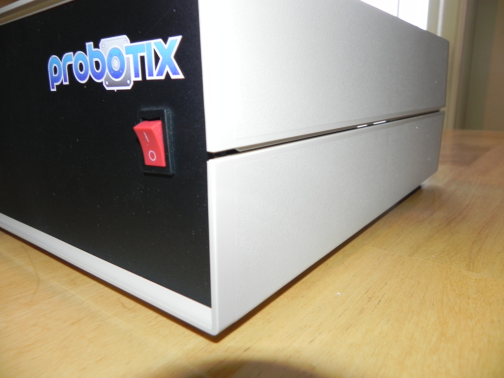
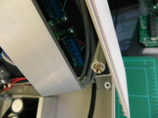
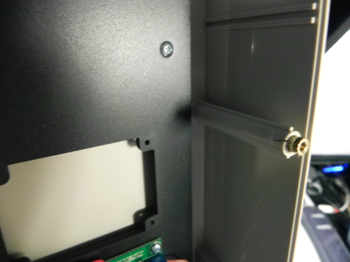
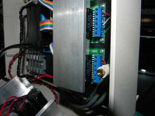
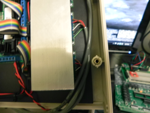
Everything in this box was stuffed into place as if it belonged there. Plenty of Styrofoam was used to protect the contents but, shipping companies sometimes do not handle your packages as if it were their own and thus, damage sometimes occur. That is exactly what happened to the control box that houses the stepper controller, stepper driver and power supply. When I removed it from the box I noticed that the top lid did not seat all the way down on the right side. Now, my first impression was maybe it just wasn’t screwed down tight when it was assembled. However, I would later find that assessment to be wrong. Below are some pictures of what I discovered:
Here is what I discovered when I opened the case:
There is a silver lining in all of this…
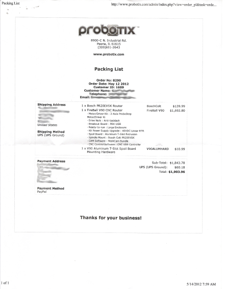
The fine folks at Probotix was quick to respond to my email and assured me that a replacement lid would be sent out to me in the mail. So far, I am very impressed with Probotix as their support is hands-down A+. I’ll continue tomorrow with unboxing and inspecting the remaining components but, for now I’ll end this post with a copy of my receipt as proof (IMO) that you can probably get a quality entry level machine on a budget. Hopefully I don’t wind up eating my words.
— Day 2: 01 June 2012:
I got more accomplished today than I thought I would be able to do. I finished unpacking and inspecting the remainder of the parts and laid them out on my work table (kitchen table). Next, I loaded up the Probotix website and pulled up the assembly manual. I’d like to note that the current version of the V90 is somewhat different from what is pictured in the build guide however, it is not difficult to figure out those differences and make adjustments along the way. You can always reference the V90 Yahoo support forum with any questions you may have (so far, so good).
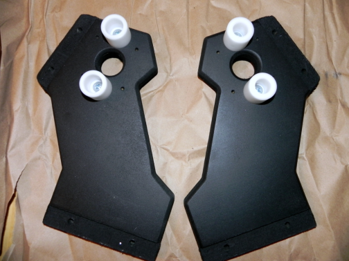
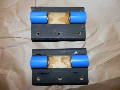
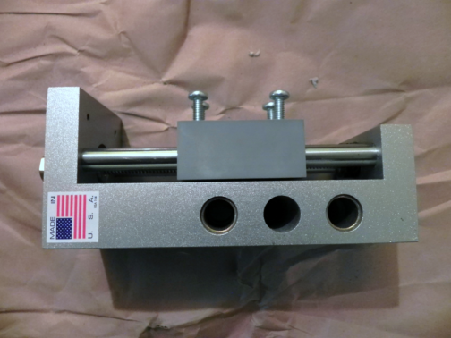
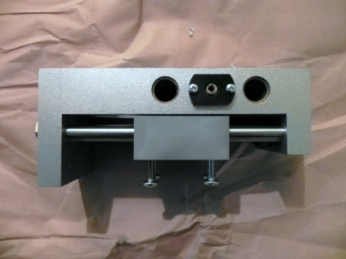
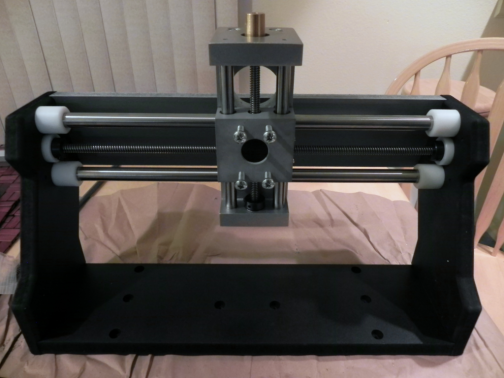
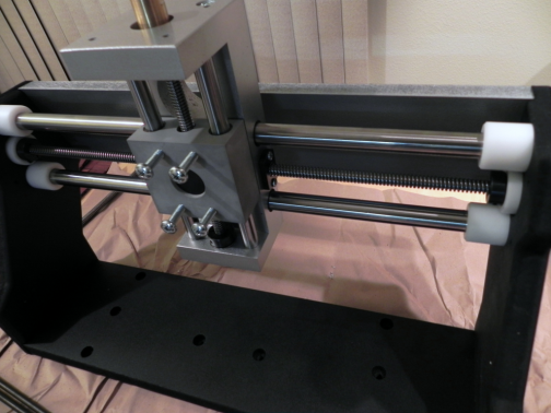
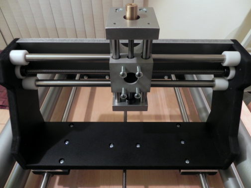
I started by assembling the gantry:
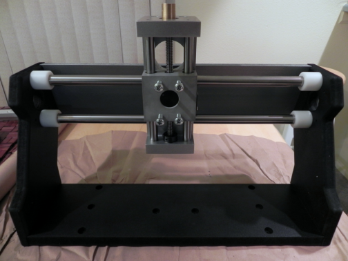
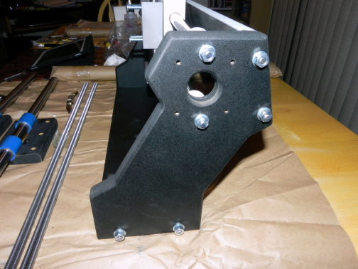
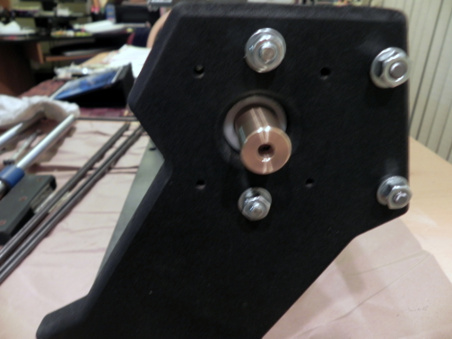
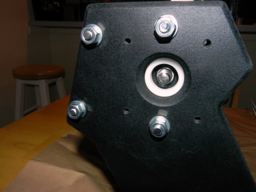
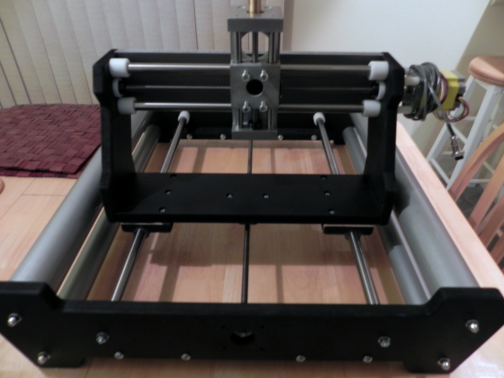
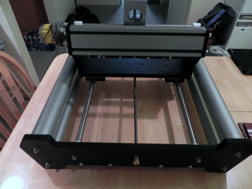
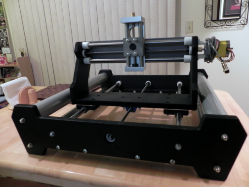
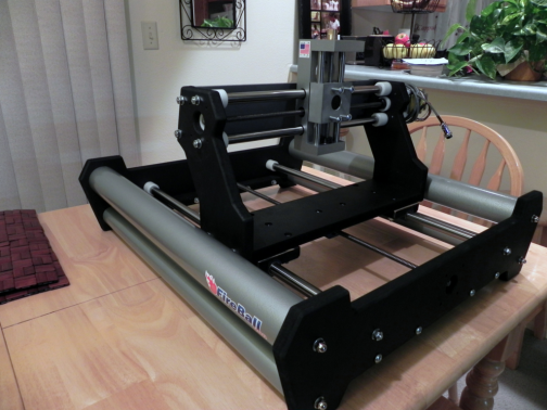
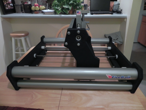
Next, I assembled the base. It was a little painful trying to get the tension rods to seat through the two holes on the opposite ends of the rail ends. The frame is held together by a combination of the tension rods and the painted PVC pipe. The tension rods are fed through one end of the rail, through the inside of the PVC pipe and out the other rail. I’m sure I spent around 1/2 hour trying to do this. Oddly enough, there were two nuts missing and two extra acorn nuts. Not a big deal as I just scrounged around my junk drawer for some replacements.
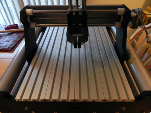
Here is the assembled base with the gantry installed:
I still need to install the rest of the stepper motors and make some adjustments to align everything.
— Day 3: 02 June 2012:
Got the machine fully assembled and operational (minus adjustments). There were a few gotchas today that took me some time to figure out. This is a case of lack of updated documentation from Probotix. I opted to purchase the aluminum extrusion spoil board and assumed that the mounting would be similar to the MDF version. Of course I needed to assemble the board since it came wrapped in four separate sections. I pulled up the web site and searched for some assembly instructions for the aluminum board but, none are available. I eye-balled the screw mounts on the end pieces and figured out how the spoil board was supposed to go together. No problem there but, I had to make multiple adjustments to the metal bracket that mounts to the underside of the spoil board to hold it all together. This metal bracket slides into the T-slots on the board and is held in place with screws and T-nuts. One interesting point I find odd is you can order the aluminum spoil board as an upgrade option with the CNC kit however, the mounting hardware has to be purchased separate.
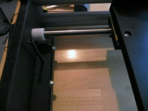
Okay, spoil board is together now and, after multiple attempts, I was able to get the brackets adjusted so that the board would fit onto the machine. I figured I was in the home stretch and attempted to secure the spoil board to the frame of the machine with the 4″ hex cap screws when I realized the screws do not screw all the way through the nut plates. Hmm, what now? I searched the internet and remembered the V90 Yahoo support group. A quick post and a few searches found the answer…I needed to remove the nut plates from the frame and run the 4″ screws through the bare holes into the spoil board. I removed the nut plates by threading one of the 4″ screws and tapping on it with a rubber mallet. The below picture shows the mounting location and the screw threaded so I can remove the nut plate:
Apparently, that light tapping with the rubber mallet was enough to cause one of the screws to shorten and I did not figure this out until the other three were installed. Nonsense, Probotix must have sent me a 3.5″ screw instead of the 4″ needed. I’m now up to three substitute parts of my own..the two washers from day 2 that was wrong and now a wrong size screw for the spoil board. Still not a big issue as I live 10 minutes from Lowe’s and I was looking for a reason to spend some money any way.
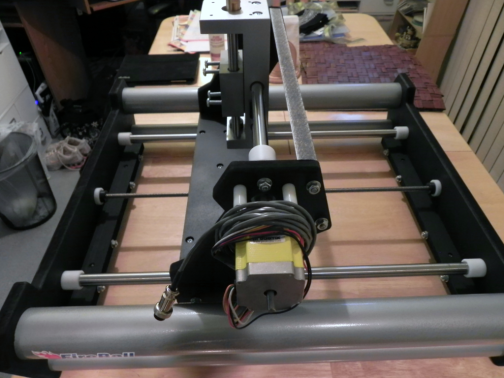
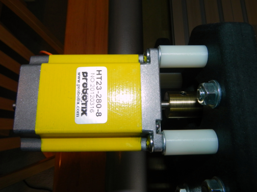
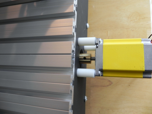
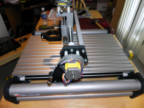
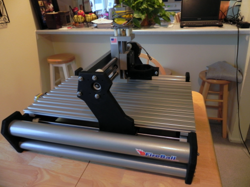
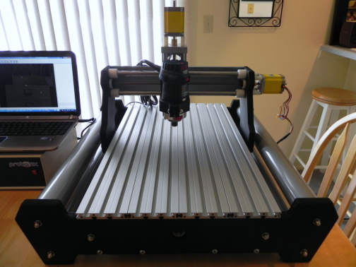
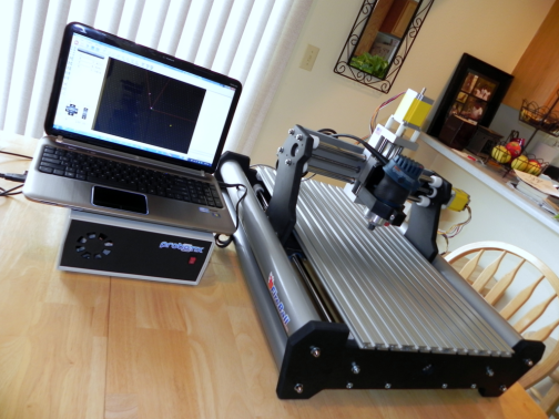
The Spoil board is now mounted and, after having to grind the screw heads down some, all of the stepper motors are mounted. Next, I installed the spindle and the router. The machine is now mostly complete minus whatever adjustments I’ll need to make during testing. Here are some pictures:
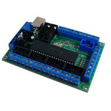
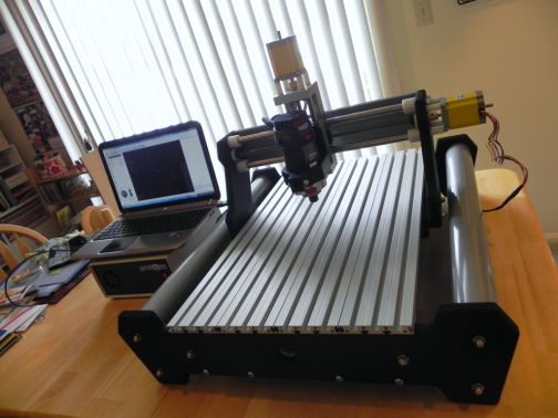
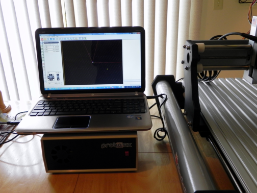
Time to connect up the controller box, grab my laptop and install the CNC-USB software. Yep, no parallel port and one is not needed. I’m using a USB CNC controller from Planet CNC. I’m actually using a version that was customized by Probotix and I have to say I really like it so far. Here is the controller and my setup:
I ran the machine through some initial manual jogging using the software and everything ran smooth. I need to work out how I am going to mount some limit switches (they are not included with the machine). I am considering using the CNZ1120 photo interrupter boards I developed instead of using mechanical switches. Well, that is all for day 3.
— Day 4: 22 June 2012:
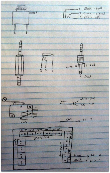
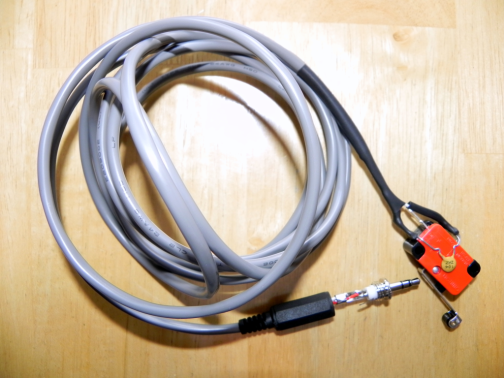
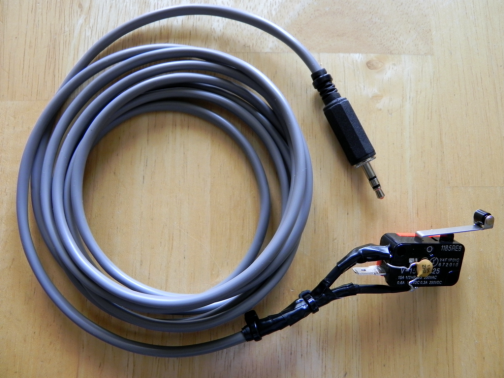
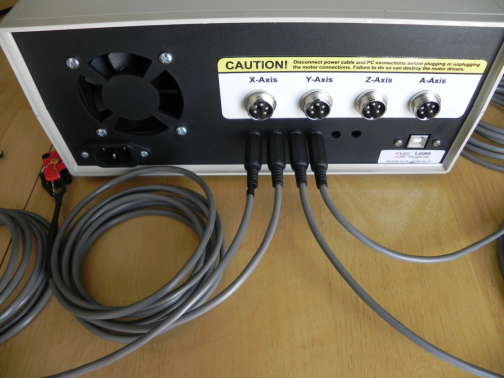
Today I got all of the limit switches wired and soldered. I added 1/8″ stereo headphone jacks to the rear of the controller case and wired them to the CNC-USB limit switch screw terminals. I only wired five switches (X- : X+, Y- : Y+, Z+) as we don’t need one for the the Z- as the tool head would more than likely run into the cut material or spoil board before the lower limit is reached.
I decided to go with mechanical switches instead of the optical boards I described on day 3. However, I did wire the associated connectors with a signal, +5V and GND connection in case I change my mind later.
Here is a rough sketch of the wiring:
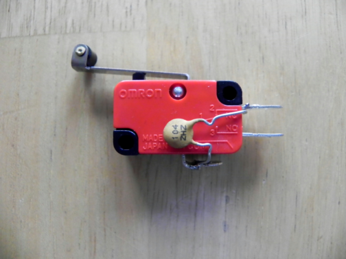
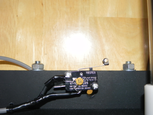
Here are some pictures of the completed limit switches:
There is a 0.1uF capacitor soldered across the COM and NC terminal of the switch. This capacitor aids in switch debounce.
Here is a picture of the almost completed control box (need to add the Z-Axis and E-Stop connections):
I still need to mount the limit switches onto the machine and make some software adjustments but, I’ll save that for another day.
— Day 5: 24 June 2012:
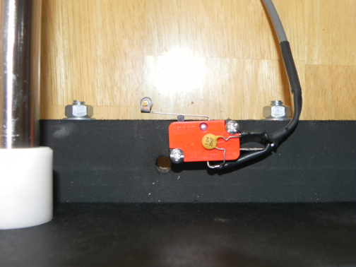
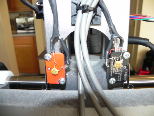
I got all of the limit switches mounted to the machine today. I spent some time yesterday trying to figure out where and how I wanted to mount the switches. I also needed to find an easy way to actuate them when the machine reaches a limit. I scrounged around in my junk parts bin and came up with some pretty neat methods on how to actuate the switches at each limit. The main requirements of my chosen scheme is to make it look neat and keep it functional.
Here are the results:
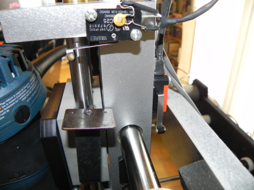
Y+ limit switch
Y- limit switch
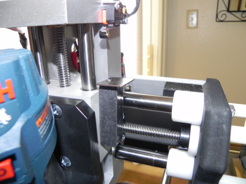
X+ and X- limit switches
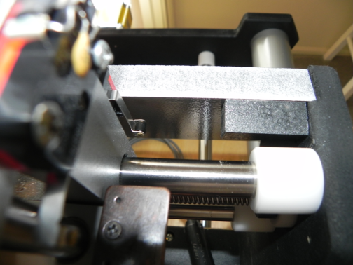
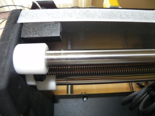
I used some strips of wood I got in a pack from Hobby Lobby to make the limit switch actuator blocks. I painted them with some Hammer Mill black metal texture paint and glued them to the CNC frame.
X+ limit switch actuator block
X- limit switch actuator block
Z+ limit switch actuator block
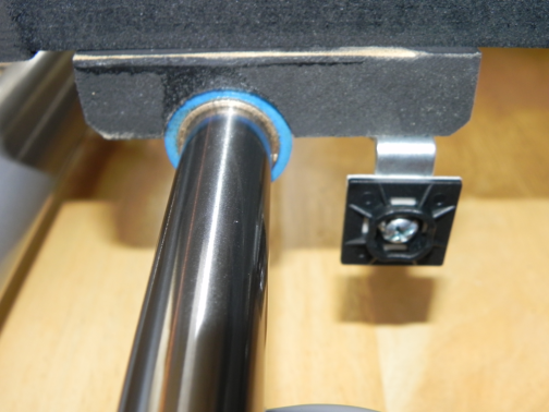
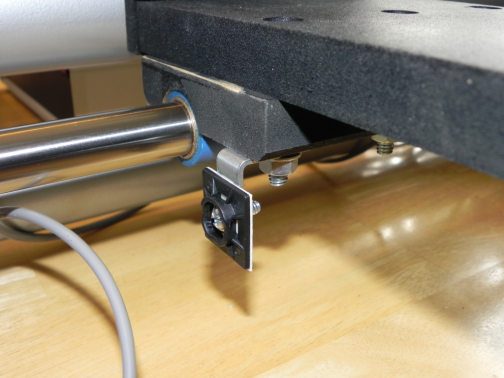
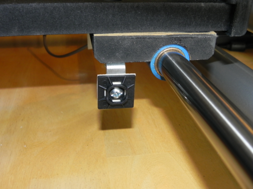
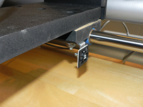
I used some L-brackets, screws and zip tie mounting bases for the Y-Axis limit switch actuators. The L-brackets are attached to the screws on the gantry mounting plates. The zip tie mounting bases provide a surface area to actuate the limit switches.
Y+ limit switch actuator plate
Y- limit switch actuator plate
All that is left is to secure the cabling and make the appropriate adjustments in the software for the limit/home switches. I found a pretty good tutorial on how to configure the CNC-USB application for the switches. This tutorial can be found here.
That wraps up today’s tinkering. I’ll make the applicable software adjustments on day 6 and run through the homing sequence.
Related Links:
Probotix FireBall V90 Assembly Instructions
FireBall CNC Yahoo Support Group
Make: Kit Reviews – FireBall V90 CNC Router Kit

Hi!
My name is Jose, and I´m from Spain.
I would like to purchase a Fireball v90. I am completely newbie to CNC Routers, and I have lots of doubts! I am on yahoo support group and other forums, but some doubts are still uncleared, specially the ones concerning choosing usb or parallel option, the system requirements, software to use, etc.
I will use the Fireball for scale models applications, check my youtube channel http://www.youtube.com/user/SceneryPlanetTV for more details.
What are your feelings about fireball v90? Do you think it worths the money? What CAD/CAM software do you prefer?
Thank you very much!
I selected the USB option as most computers today do not have parallel ports. In addition, I wanted to be able to use my laptop for portability. I really like the USB-CNC option as it is very robust and continually updated. Check out the CNC-USB website as there are different versions of the USB controller outside of what Probotix offers. I went with the option from Probotix as it does everything I need. The machine itself is very solid and easy to put together even though it is made from MDF. You can contact them if you want other options added to the system before it ships such as pre-mounted limit switches and modifications to the control box for limit switch connectors. I did not select any of these options and elected to do the modifications myself. I ordered the Meshcam software with the package but, I actually prefer V-Carve Pro for CAM. For CAD, I am using a combination of BoBCAD and FreeCAD.
I believe this machine is well worth the money for entry level CNC. A few recommendations if you decide to purchase are:
1: Use locktite or locknuts once the machine has been squared. The stock nuts that ships with the CNC will work themselves loose over time.
2: If you plan to have the software control the spindle and purchase the relay controller from Probotix, have them mount and wire it in the control box for you.
3: You’ll want to plan out where you want to mount your limit switches, how you will wire them and where you will place the E-Stop button.
Hope this information helps you out in your decision.
Hi again! Thank you for your quick answer! Your advaice is really helpful.
I will contact again Probotix staff to learn more about the premounted limit switches options.
Thank you very much!
I´ll keep an eye on your blog, cool stuff!