Introduction
A little while ago a fellow robot builder that goes by the signature of ignoblegnome (IG) did a review for me on my version of a minimalist Arduino clone designed to be used for prototyping and finished projects. The board design allows the Hobbyduino Mini to be used on a breadboard by soldering pin headers to the I/O sockets or in a finished project by attaching wires. IG also passed along some great suggestions for future versions. I took the suggestions he made and modified the original design. Below is the 3rd revision of the Hobbyduino Mini. Oh yeah, I also wanted to mention that I soldered these boards using my DIY Reflow Oven (I’m still getting the documentation together but the boards look really good).
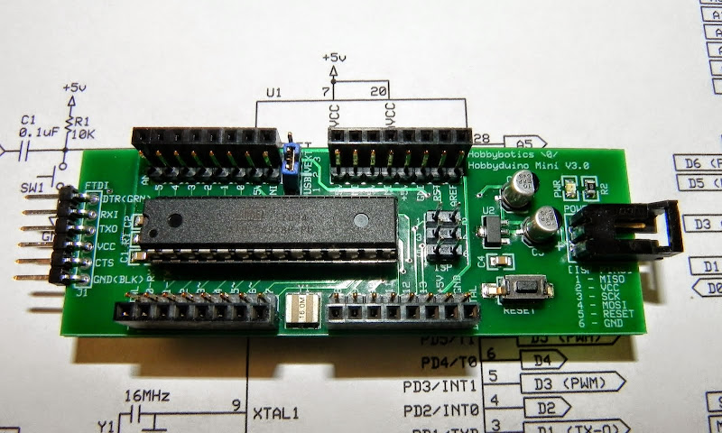
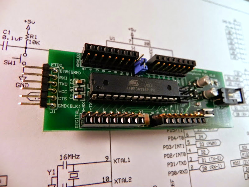
Just as the original design, the current version does not contain the circuitry for USB communication. I opted to rely on the FTDI RS232R-to-serial boards to handle the USB-to-Serial protocol. Here is the one I use but, others are available.
The Hobbyduino Mini V3.0 contains an on-board voltage regulator that accepts 7 – 18V and outputs 5V @ 1A. Optionally, power can be provided by the USB port when the FTDI adapter is plugged into the board. Be advised, you can damage the USB port if more than 500mA is drawn from it.
Specifications
- ATMega328 processor running at 5V
- 16 MHz resonator
- Input voltage 7-18V
- Output voltage 5V @ 1A
- USB or external power (requires FTDI adapter for USB power)
- Size: 1.1875W” x 3.5L”
- Digital (0 – 13), analog (0 – 5), serial, and I2C pins brought out to pin headers
- Designed to plug into a breadboard for easy prototyping
- Configured for auto-reset after programming
- Manual reset button
- 6-pin ISP connector
Documentation
- Schematic – PDF
- PCB – PDF
- Schematic – SCH
- PCB – PCB
- Mechanical Drawing – DXF
- Bill of Materials – TXT
The schematic and PCB was developed with the freely available ExpressPCB software.
Build It
Reference the B.O.M above for a list of the parts necessary to complete the Hobbyduino Mini.
Most of the components are surface mount devices (SMD) except for the connectors and pin headers. As such, soldering may take a little more time and a little more experience. I recommend starting with the low profile components first such as the 0805 resistors and capacitors. I also recommend that consideration be given to the components that may be a little more difficult to solder because of location, such as the voltage regulator that is surrounded by the two 10uF capacitors. The last device that should be installed on the board is the ATMega328 microcontroller. The ATMega is susceptable to what is known as electrostatic discharge (ESD) which could damage the component without any visual signs.
Reference the below schematic and layout file for component locations.


IG recommended that I change the location of the FTDI breakout labels as they were hidden under the right-angle pin header on the board. The FTDI labels on the revised board mirror that of the FTDI basic breakout board and the FTDI breakout cable from SparkFun. You’ll notice that two of the pins are also labeled (GRN) and (BLK) to match the color coding of the FTDI breakout cable. This should eliminate any confusion on which way the breakout cable and/or the breakout board plugs into the FTDI header on the Hobbyduino.
Before change:

and After:
IG also recommended that I move all of the digital pins to one side of the board, label the pins that also function as PWM, and breakout the RESET and AREF pins to separate headers. You can see the before and after below.
Before change:

And after:

Each of the PWM pins are labeled with a tilde ‘~’ just like on the UNO. The meaning of the tilde is described on the underside of the board for those that may be unfamiliar with the UNO.
There was a design flaw in the original board that did not affect operation but, could be a problem if you decided to run a board off of an external supply at the same time you were connected to the USB port on your computer through the FTDI connection. This is a no no as it has the potential to force current onto the USB port and possibly fry it. I did not have that happen but, it was something I should have caught in the original design. I fixed it by adding a jumper to allow the board to be powered from the USB port or external power. Now, the board can be connected to the USB port and powered externally without the worry of forcing current onto the port (provided you remember to set the jumper).
Lastly, IG suggested I reposition the positive and negative labels for the external power connector as the labels would be covered if a connector is soldered onto the board. I informed him that I caught that one and would fix it on the next design. See below:
Before:

After:

You’ll notice a 6-pin header just below the ATMega328 IC labeled as ISP. That connector will allow you to use the Hobbyduino with ATMega chips that do not have the Arduino bootloader installed by programming them with an external programmer such as theSTK500 sold by SparkFun.
Finally, the board can be configured in a number of different ways to facilitate use. I soldered male headers and female headers onto the board in the pictures above. The female headers are the same that are used on the Arduino boards and shields to allow stacking. This decision will become more evident when I introduce the Hobbyduino Bootloader ISP shield. Ofcourse, the board could be configured with any combination of headers or none at all if it will be used in a finished project. IG also asked me why I went with a 28-pin ATMega328 dip IC instead of using its SMD variant and my response was to allow the IC to be easily removed from the board. There may be situations where you let the magic smoke out or simply want to wire the board up as an ISP to load the Arduino bootloader on other chips. I do intend to create a board with the SMD IC later on.
Use It
I recommend you look over your solder connections before you apply power to the board. This will give you an opportunity to detect and correct any bad solder joints or solder bridges that could possibly let the smoke out. Once that is complete there are a few tidbits we need to take care of before we can make stuff. We’ll need to get some software (free of course) and configure some settings.
1. Go here and download the latest version of the Arduino Ide.
2. Plug the FTDI Serial-to-USB adapter into an available USB port on your computer. The drivers will automatically be downloaded and installed.
3. Go to Device Manager on your computer and expand the Ports (COM & LPT) field. Right-click on the USB serial port and select -> properties -> port-settings tab -> advanced. Set the baud-rate to the appropriate setting for your controller.
4. Extract the compressed file to a location on your computer and launch the “arduino.exe” file.
5. In the Arduino Ide, select Tools -> Board -> Arduino Duemilanove or Nano w/ ATmega328.
6. Ensure the correct serial port is selected in the Arduino Ide.
You are now ready to upload and test your first sketch on the Hobbyduino Mini.
| /* | |
| Blink | |
| Turns on an LED on for one second, then off for one second, repeatedly. | |
| This example code is in the public domain. | |
| */ | |
| void setup() { | |
| // initialize the digital pin as an output. | |
| // Pin 13 has an LED connected on most Arduino boards: | |
| pinMode(13, OUTPUT); | |
| } | |
| void loop() { | |
| digitalWrite(13, HIGH); // set the LED on | |
| delay(1000); // wait for a second | |
| digitalWrite(13, LOW); // set the LED off | |
| delay(1000); // wait for a second | |
| } |
1. Launch the Arduino Ide, click on File -> Examples -> 1.Basics -> Blink. A new Ide window will open with the selected sketch loaded.
2. Connect a LED and resistor to digital pin 13 like below.
3. Click the upload button and the sketch will be uploaded to the board. You’ll need to do a little troubleshooting if the sketch fails to upload. I recommend checking for the correct serial port and board within the Arduino Ide.
4. If all is successful, the LED attached to digital pin 13 will begin to pulse on for 1 sec and off for 1 sec.
This completes the basic functionality test for the Hobbyduino Mini. Checkout the video to see it in action.
That’s all for the Hobbyduino Mini V3.0. I’ll introduce the Hobbyduino Bootloader ISP shield in another post.
Related Links
Disclaimer
This example shows hardware and software used to implement the design. It is recommended the viewer use sound judgment in determining and/or implementing this example for any particular application. This example may include information from 3rd parties and/or information which may require further licensing or otherwise. Additional hardware or software may be required. Hobbybotics or any affiliates does not support or warrant this information for any purpose other than a design example and takes no responsibility for any mishaps (none being implied).
