Adjusting the Backlight Brightness
Defining Custom LCD Characters
Introduction
The majority of the projects I design provide some sort of informational feedback to the user. The primary device I use to provide feedback is a Liquid Crystal Display (LCD) based on the Hitachi HD44780 LCD command set. These LCDs use a standard 16 contact interface and are known as parallel devices.
The LCD can be operated in two modes: 8-bit and 4-bit, respectively. A minimum of 11 microcontoller pins are needed for 8-bit mode and 7 are needed for 4-bit mode. Dedicating 11 or 7 pins for the LCD might pose some unwanted limits on one’s design thus, we will create a serial LCD controller that only needs one output pin.
The Hobbybotics Serial LCD controller was designed as an alternative to some of the better-known controllers at a fraction of the cost. The design and feature set is as robust as other well-known controllers such as those available from Parallax Inc and Scott Edwards Electronics.
** NOTE **
- The design presented here is just a prototype. I intend to refine the design and present it in another article.
- The example code snippets assume that the controller is being interfaced to a Parallax BS2. Reference the documentation for your chosen device to figure out how to send serial data.
Features
- Wraps text to the next line automatically
- Works at 9600, 19200, 38400, and 57600 baud
- Last selected baud rate is stored in EEPROM and recalled upon power up
- Cursor position is user settable
- Allows up to eight custom characters to be defined
- LCD backlight is software controllable and can be store in controller
- Robust command set
- Easy to implement control scheme in software or from microcontroller
- Displays ASCII character set directly to the display
Connections
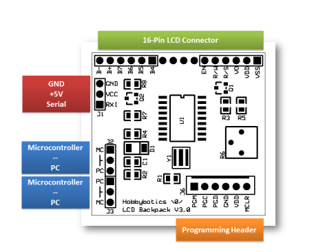
Connecting the Serial LCD Backpack to a microcontroller or PC is straightforward, requiring just three connections, +5V, GND and RX. See figure and tables for typical connections.
Table 1 – J1 Power/Serial Connector (4-pin)
| Connector | Label | Function |
| J1-1 | GND | Supply GND. Connect to microcontroller GND or DB9-5 of computer. |
| J1-2 | VCC | Supply (+). Connect to + supply of microcontroller. |
| J1-3 | RXI | Connect to microcontroller serial pin or DB9-3 of computer |
Table 2 – J2 Inverted/Non-Inverted Serial Selection Jumper (3-pin)
| Connector | Label | Function |
| J2-1 to J2-2 | Non-Inverting | Jumper if connecting to a microcontroller. |
| J2-3 to J2-2 | Inverting | Jumper if connecting to RS232 device (such as a serial port on computer). |
Table 3 – J3 Inverted/Non-Inverted Serial Selection Jumper (3-pin)
| Connector | Label | Function |
| J3-1 to J3-2 | Inverting | Jumper if connecting to RS232 device (such as a serial port on computer). |
| J2-3 to J2-2 | Non-Inverting | Jumper if connecting to a microcontroller. |
Table 4 – J6 (ICSP) In Circuit Programming Connector (6-pin)
| Connector | Label | Function |
| J6-1 | PGM | N/A |
| J6-2 | PGC | Connected to microcontroller RB6 or PGC pin |
| J6-3 | PGD | Connected to microcontroller RB7 or PGD pin |
| J6-4 | GND | Connected to GND and microcontroller GND pin |
| J6-5 | VDD | Connected to +5V and microcontroller VDD pin |
| J6-6 | MCLR | Connected to microcontroller MCLR pin |
Table 5 – J4 and J5 LCD Connector (16-pin)
| Name | LCD Pin | Controller Pin | Level | Function |
| VSS | 1 | N/A | 0.0V | Supply GND connection for logic/LCD |
| VDD | 2 | N/A | 5.0V | Supply voltage for logic/ LCD (+) |
| Vo | 3 | N/A | 0.3V | LCD contrast adjust |
| RS | 4 | B0 | H/L | Selects LCD register |
| R/W | 5 | B2 | H/L | Read/Write signal |
| E | 6 | B1 | H/L | Chip enable signal |
| DB0 | 7 | N/A | H/L | Data Bit 0 |
| DB1 | 8 | N/A | H/L | Data Bit 1 |
| DB2 | 9 | N/A | H/L | Data Bit 2 |
| DB3 | 10 | N/A | H/L | Data Bit 3 |
| DB4 | 11 | B4 | H/L | Data Bit 4 |
| DB5 | 12 | B5 | H/L | Data Bit 5 |
| DB6 | 13 | B6 | H/L | Data Bit 6 |
| DB7 | 14 | B7 | H/L | Data Bit 7 |
| A (+) | 15 | N/A | 5.0V | LED Backlight (+) |
| K (-) | 16 | B3 | H/L | LED Backlight (-). PWM controlled |
Interface Specifications
The Serial LCD is setup for a default baud rate of 9600 baud. The baud rate can be set to values of 9600, 19200, 38400, 57600 and 115200. This is accomplished by sending the sync byte 254 followed by the commands listed in the table below. The last selected baud rate is saved in EEPROM and recalled on the next power recycle. Ensure the connection to the serial port is refreshed at the new rate to ensure the devices stay in sync.
Example 1: Serout TxPin, i9600, [254, 11, 1] ‘Set baud to H19200
Table 6 – LCD Baud Rates
| Command 1 | Command 2 | Result |
| 11 | 0 | H9600 |
| 11 | 1 | H19200 |
| 11 | 2 | H38400 |
| 11 | 3 | H57600 |
Operating the LCD
On power up the LCD goes through an initialization routine to allow the applied voltage to stabilize. To allow for proper initialization ensure at least a 100ms delay before data/commands are sent.
The following are the instructions for the Hobbybotics LCD controller:
Table 7 – LCD Controller Instruction Set
| Command | Command Byte |
| Clear display | <0> |
| Set cursor home (top leftmost position) | <1> |
| Move cursor left or right | <2> <0 or 1> |
| Scroll display left or right | <3> <0 or 1> |
| *Set cursor position | <4> <position> |
| Display properties:Display offDisplay onBlink onCursor onCursor and blink on | <5> <0><5> <1><5> <2><5> <3><5> <4> |
| Delete character | <6> |
| Write custom character to CGRAM | <7> <Address 0 – 7><chr 0><chr 1><chr 2><chr 3><chr 4><chr 5><chr 6><chr 7> |
| Display custom character | <8> <Address 0 – 7> |
| Set backlight on or off | <9> <0 or 1> |
| Set backlight brightness | <10> <level 0 – 255> |
| **Set baud rate:9600192003840057600 | <11> <0><11> <1><11> <2><11> <3> |
| Save current backlight setting | <12> |
| Recall saved backlight setting | <13> |
| Clear selected line | <14><Row 1 – 4> |
| Carriage return | <15> |
| Scroll cursor up | <16> |
| Scroll cursor down | <17> |
| Enable/Disable splash screen | <18><0 or 1> |
| All commands are preceded by the command byte 254 or $FE*Refer to LCD specifications for pixel mappings. Table 7 lists a typical mapping for a 4×20 character LCD.**Ensure serial connection is refreshed after changing LCD baud rate. | |
Displaying Text
To display a character on the LCD, send the ASCII code of that character at the correct baud rate. Once received, the LCD displays the character at the current cursor position and moves the cursor one position to the right. If turned on, the current cursor position will be displayed by an under-carat. When the characters reach the end of the first line the LCD automatically wraps the cursor position to the first character of the next line.
Example 2: Serout TxPin, i9600, [“Hobbybotics.com”]
Position the Cursor
There are numerous commands for positioning the cursor on the display. The cursor will automatically advance one space to the right after each character. Extended commands allow the cursor to be advanced left or right one space and positioned at any location on the display. If the cursor position is set in a location where there is existing text, the character will be overwritten starting at the cursor position whenever characters are received.
Example 3: Serout TxPin, i9600, [254, 2, 0] ‘Move cursor left
Example 4: Serout TxPin, i9600, [254, 2, 1] ‘Move cursor right
The cursor can be directly placed at any position on the display with the position cursor command. Refer to the below table for an example LCD mapping.
Table 8 – Typical 4×20 Pixel Mapping
| Line 1 | ||||||||||||||||||||
| HEX | 00 | 01 | 02 | 03 | 04 | 05 | 06 | 07 | 08 | 09 | 0A | 0B | 0C | 0D | 0E | 0F | 10 | 11 | 12 | 13 |
| DEC | 00 | 01 | 02 | 03 | 04 | 05 | 06 | 07 | 08 | 09 | 10 | 11 | 12 | 13 | 14 | 15 | 16 | 17 | 18 | 19 |
| Line 2 | ||||||||||||||||||||
| HEX | 40 | 41 | 42 | 43 | 44 | 45 | 46 | 47 | 48 | 49 | 4A | 4B | 4C | 4D | 4E | 4F | 50 | 51 | 52 | 53 |
| DEC | 64 | 65 | 66 | 67 | 68 | 69 | 70 | 71 | 72 | 73 | 74 | 75 | 76 | 77 | 78 | 79 | 80 | 81 | 82 | 83 |
| Line 3 | ||||||||||||||||||||
| HEX | 14 | 15 | 16 | 17 | 18 | 19 | 1A | 1B | 1C | 1D | 1E | 1F | 20 | 21 | 22 | 23 | 24 | 25 | 26 | 27 |
| DEC | 20 | 21 | 22 | 23 | 24 | 25 | 26 | 27 | 28 | 29 | 30 | 31 | 32 | 33 | 34 | 35 | 36 | 37 | 38 | 39 |
| Line 4 | ||||||||||||||||||||
| HEX | 54 | 55 | 56 | 57 | 58 | 59 | 5A | 5B | 5C | 5D | 5E | 5F | 60 | 61 | 62 | 63 | 64 | 65 | 66 | 67 |
| DEC | 84 | 85 | 86 | 87 | 88 | 89 | 90 | 91 | 92 | 93 | 94 | 95 | 96 | 97 | 98 | 99 | 100 | 101 | 102 | 103 |
A 4×20 character LCD is mapped like two separate 2×16 character LCD’s. As such, once the cursor reaches the end of line 1 (position 19), it will normally wrap to line 3 (position 20). However, the LCD controller corrects this so that the cursor will wrap to line 2 (position 64).
Example 5: Serout TxPin, i9600, [254, 4, 65] ‘Line 2, position 2
Setting Display Properties
Various display modes can be set for the LCD. These include turning the display on/off, turning on/off a blinking block cursor, turning on/off an under-carat cursor, and turning on both the block and under-carat cursors. Turning off the display will not darken the display but will hide any text. Characters can still be sent to the display when it is turned off but will not be visible until the LCD is enabled.
Example 6: Serout TxPin, i9600, [254, 5, 0] ‘Disable display
Example 7: Serout TxPin, i9600, [254, 5, 1] ‘Enable display
Example 8: Serout TxPin, i9600, [254, 5, 3] ‘Cursor on
Turning ON..OFF the Backlight
The LCD backlight can be turned on/off using a simple command. Refer to the below examples for usage.
Example 9: Serout TxPin, i9600, [254, 9, 0] ‘Backlight off
Example 10: Serout TxPin, i9600, [254, 9, 1] ‘Backlight on
Adjusting the Backlight Brightness
The LCD backlight is used to illuminate the display. The brightness can be varied from 0 to 100% by passing a value 0 – 255. The current brightness setting can be stored in the controller EEPROM by sending command <12> and recalled by command <13>. The last stored value is also recalled on the next power cycle. Refer to the below examples for usage.
Example 11: Serout TxPin, i9600, [254, 10, 127] ‘50% brightness
Example 12: Serout TxPin, i9600, [254, 10, 255] ‘100% brightness
Example 13: Serout TxPin, i9600, [254, 12] ‘Store level
Example 14: Serout TxPin, i9600, [254, 13] ‘Recall level
Adjusting the Contrast
The controller is equipped with a 10k potentiometer to control the contrast of the LCD. This may need to be adjusted for optimum viewing.
Defining Custom LCD Characters
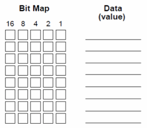
The character generator ram (CGRAM) built into the HD44780 compatible LCD controller allows eight custom characters to be stored into its static ram. These characters are available so long as power is applied to the display. Each byte of CGRAM is mapped to a 5 x 8 row/column of pixels. Custom defined characters correspond to ASCII codes 0 through 7. Writing to CGRAM is accomplished by sending the address location followed by eight byte values that correspond to the created character. Refer to the below figure for an example custom character.
 |
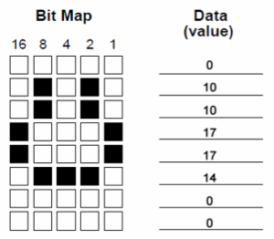 |
The custom character would be stored in the LCD memory using the below formatting.
Example 15: Serout TxPin, i9600, [254, 7, 0, 0, 10, 10, 17, 17, 14, 0, 0] ‘Write to address 0
The above example would write the example custom character at memory address 0. This leaves seven memory address locations available for custom characters.
Displaying a custom character stored in CGRAM can be accomplished simply by recalling the associated memory location.
Example 16: Serout TxPin, i9600, [254, 8, 0] ‘Display character @ 0
Reference figure 1 for a typical LCD character set. Add the row and column values for a given character.
Figure 1 – To find the ASCII code for a given character, add the row and column numbers. CGRAM custom characters occupy locations 0 -7.
Controller Circuit
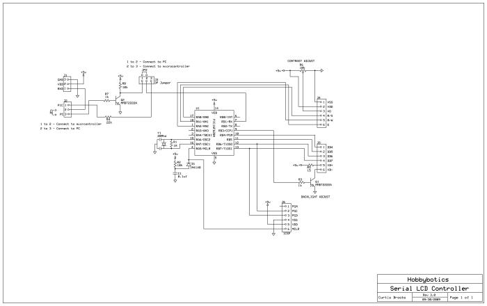
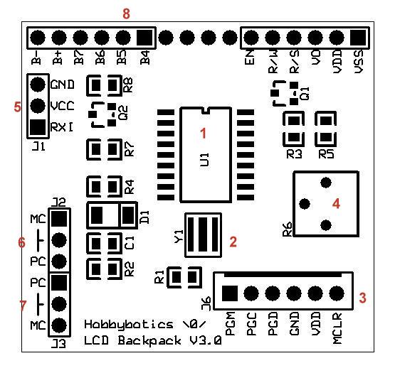
The controller circuit consists of a PIC16F628A, a 10K contrast potentiometer, a transistor that allows ON..OFF/PWM of the LCD backlight and a transistor that is used to convert RS232 levels from a PC serial port to 5V TTL levels. There are two jumpers in the schematic that are used to set whether the LCD will be controlled by a PC serial port or from a serial connection on a microcontroller. JP1 is placed across J2 pins 1..2 if the LCD is controlled by a microcontroller or J2 pins 2..3 if the LCD is connected to a PC serial port. JP2 is placed across J3 pins 1..2 if the LCD is connected to a PC serial port or pins 2..3 if controlled by a microcontroller. Connecting JP2 across J3 pins 2..3 bypasses transistor Q2. This jumper setting is essential for proper controller operation when connected to a microcontroller.
Below is a description of the main components and features:
| Item | Function |
| 1 | PIC16F628A |
| 2 | 20 Mhz Resonator |
| 3 | ICSP Header |
| 4 | 10K Contrast Potentiometer |
| 5 | Power and Serial Header |
| 6, 7 | Interface Select Jumper |
| 8 | 16P LCD Connector |
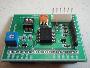
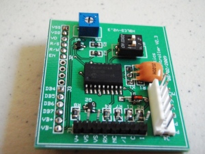
Here are some a pictures of a previous revision board:
 |
 |
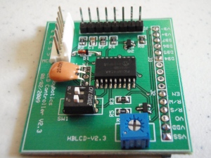 |
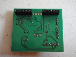 |
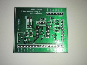 |
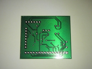 |

|
|
Documentation
- Board Files – Link
The schematic and PCB was developed with the freely available ExpressPCB software.
The project files and future updates can be found on my github page.
Build It
Reference the B.O.M above for a list of the parts necessary to complete the Hobbybotics Serial LCD Controller V3.0 board.
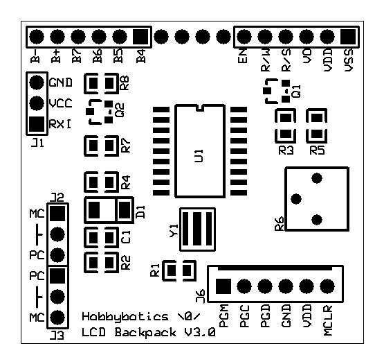
Reference the below layout file for component locations.
Firmware
The firmware for this project was developed using PicBasic Pro V2.60 from microEngineering Labs. You will need to place both *.pbp files into the same directory in order for the code to properly compile.
Code Snippets:
I won’t rehash all of the code here as you can view the complete source for that but, I do want to point out some of the key routines.
Defines:
The following DEFINE statements need to be adjusted for the type of LCD you are developing for. Specifically, the number of lines the particular LCD has (2-line or 4-line). The other statements determine what ports will be used to interface to the LCD. The default firmware is set up for a 4×20 character LCD:
| ;-----[ Includes ]--------------------------------------------------------- | |
| INCLUDE "16F628A.pbp" | |
| ;-----[ Defines ]---------------------------------------------------------- | |
| ;Define oscillator speed in Mhz | |
| DEFINe OSC 20 | |
| ;Define which port is connected to the LCD Data pins D4 - D7 | |
| DEFINE LCD_DREG PORTB | |
| ;Define starting Data bit on port (0 for 8-bit or 4 for 4-bit port) | |
| DEFINE LCD_DBIT 4 | |
| ;Define LCD Bus size (4-bit or 8-bit) | |
| DEFINE LCD_BITS 4 | |
| ;Define LCD Register Select (RS) port | |
| DEFINE LCD_RSREG PORTA | |
| ;Define LCD Register Select (RS) bit | |
| DEFINE LCD_RSBIT 0 | |
| ;Define LCD Read/Write (RW) Port | |
| DEFINE LCD_RWREG PORTA | |
| ;Define LCD Read/Write (RW) bit | |
| DEFINE LCD_RWBIT 2 | |
| ;Define LCD Enable (E) port | |
| DEFINE LCD_EREG PORTA | |
| ;Define LCD Enable (E) bit | |
| DEFINE LCD_EBIT 1 | |
| ;Define number of lines on LCD | |
| DEFINE LCD_LINES 4 | |
| ;Define LCD command delay time | |
| DEFINE LCD_COMMANDUS 2000 | |
| ;Define LCD data delay time | |
| DEFINE LCD_DATAUS 50 | |
| ;Enable serial port & continuous receive | |
| DEFINE HSER_RCSTA 90h | |
| DEFINE HSER_TXSTA 20h | |
| ;Clear overflow automatically | |
| DEFINE HSER_CLROERR 1 | |
| ;Turn off PORTA comparators | |
| CMCON = 7 |
Serial Interrupt Routine:
The firmware implements a serial interrupt routine to ensure that all of the data is captured. First, we define the interrupt handler, “ON INTERRUPT goto Serial_Interrupt” and enable interrupts on USART, “PIE1.5 = 1.” Second, we setup the baud rate flags BRGH and RCIF. Third, we designate EEPROM locations 0 and 1 for storing the baud rate. The baud rate settings are read during controller initialization and saved whenever changed. The baud rate can be changed through commands from a microcontroller or PC. Finally, we create the interrupt routine, “Serial_Interrupt:”
| ;Enable unmasked peripheral interrupts | |
| INTCON = %11000000 | |
| ;Declear interrupt handler | |
| ON INTERRUPT goto Serial_Interrupt | |
| ;Enable interrupt on USART (Serial Receive) | |
| PIE1.5 = 1 | |
| ... | |
| ;-----[ Variables ]-------------------------------------------------------- | |
| ;High Baud Rate Select bit | |
| BRGH VAR TXSTA.2 | |
| ;Receive interrupt flag (1 = full, 0 = empty) | |
| RCIF VAR PIR1.5 | |
| ;-----[ EEPROM ]----------------------------------------------------------- | |
| ;Reference labels for associated memory locations | |
| ;EEPROM locations 0 and 1 store the default baud rate value (9600 baud) | |
| _BRGH DATA @0, 0 | |
| _SPBRG DATA @1, 32 | |
| ... | |
| ;-----[ Initialization ]--------------------------------------------------- | |
| Init: | |
| ... | |
| ;Read BRGH Baud Rate Select Bit and SPBRG Register from memory. Set | |
| ;baud rate based on these values. A better understanding of these | |
| ;settings can be gathered from the selected microcontroller data sheet. | |
| ;GOSUB READ_BAUD_RATE | |
| read _BRGH, BRGH | |
| read _SPBRG, SPBRG | |
| ... | |
| ;We read BRGH and SPBRG values from EEPROM. BRGH will be 0 for low bit | |
| ;rates and 1 for high bit rates. The below routine is used to display | |
| ;the saved baud rate on initial power on of the LCD controller. This is | |
| ;to aid in pairing the correct baud rate from the controller/PC to the | |
| ;LCD controller. A Clear Screen command should be sent to the LCD | |
| ;before sending further data unless you want the baud rate to stay on | |
| ;the display. | |
| select case brgh | |
| case 0 | |
| size = 4 | |
| ARRAYWRITE baud, ["9600"] | |
| case 1 | |
| select case SPBRG | |
| case 64 | |
| size = 5 | |
| ARRAYWRITE baud, ["19200"] | |
| case 32 | |
| size = 5 | |
| ARRAYWRITE baud, ["38400"] | |
| case 21 | |
| size = 5 | |
| ARRAYWRITE baud, ["57600"] | |
| case else | |
| END SELECT | |
| end select | |
| ... | |
| ;-------------------------------------------------------------------------- | |
| ;Serial Interrupt routine | |
| ;-------------------------------------------------------------------------- | |
| ;Make sure we do interrupt our interrupt | |
| disable | |
| Serial_Interrupt: | |
| ;Check for serial input | |
| if (RCIF = 1) then | |
| ;Keep track of serial buffer | |
| index = index + 1 | |
| ;If buffer over-flows reset buffer | |
| if (index = buffer_size) then index = 0 | |
| ;Get serial input and store in array | |
| hserin [Rx_Array[index]] | |
| endif | |
| resume | |
| enable | |
That wraps up the overview of the firmware so, let’s move along to the optional Windows control application.
Software
The windows application I developed for this project allows full control over the LCD functionality. This application was developed with C# 2010.
Here is a screen capture of the application:
| Number | Description | Control Function |
| 1 | Serial Setup | Establishes a serial connection. Automatically detects available ports and saves previously used settings. |
| 2 | Text Display | Mirrors a 4×20 Character display. Allows text to be sent to each line. |
| 3 | Keypad | Controls the position of the cursor and allows characters to be deleted. |
| 4 | ASCII Characters | Sends ASCII characters to the display. |
| 5 | Back-light Adjust | Turns ON..OFF the back-light and adjusts the brightness. |
| 6 | Display Settings | Enables..Disables the display and allows the cursor type to be set. |
| 7 | Cursor Position | Set the cursor to row..column position |
| 8 | Splash Screen | Enable..Disable the default LCD start-up splash screen. |
| 9 | Custom Character Generator | Create custom up to 8 custom characters and store them in the LCD memory locations 0..7. Custom characters are only stored while power is supplied to the LCD. |
There is a lot of built in functionality that I have not covered and even though the application is robust, it is still in development. I will post future updates to my github page.
Conclusion
This project covered my design for a serial LCD controller based on a PIC16F628A from Microchip. We began by discussing the features and connections that allow the controller to be interfaced to both a microcontroller and PC serial port. Next, an explanation of the command-set was presented along with typical examples. Finally, we built the project, reviewed key points of the firmware, and presented the optional windows application. Armed with the information presented in this project, one should be able to implement a cost effective serial LCD controller and save some precious I/O pins.
Related Links
Hobbybotics Serial LCD Controller Gallery
References
- None
Disclaimer
This example shows hardware and software used to implement the design. It is recommended the viewer use sound judgment in determining and/or implementing this example for any particular application. This example may include information from 3rd parties and/or information which may require further licensing or otherwise. Additional hardware or software may be required. Hobbybotics or any affiliates does not support or warrant this information for any purpose other than a design example and takes no responsibility for any mishaps (none being implied).
