Introduction
One of the features that has made the Arduino such a success is its well thought out design that allows add-on boards called “Shields” to be attached. These shields are designed to extend the functionality of the Arduino without the complexity of having to do point-to-point wiring.
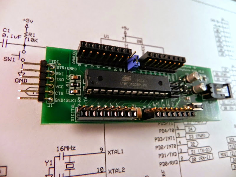
In a previous post I presented a revised version of my Minimalist Arduino Clone called the Hobbyduino Mini V3.0. Here is a picture for reference.
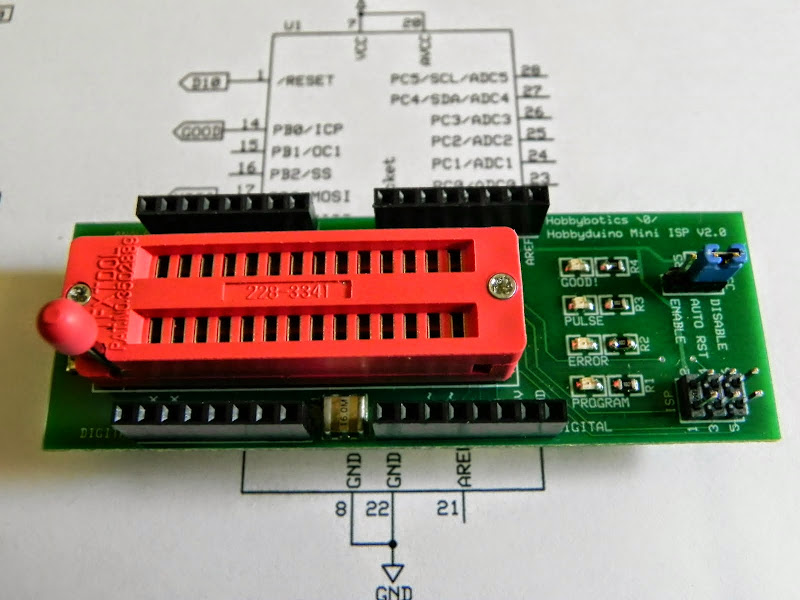
The Hobbyduino Mini allows for shields (or plugs as I call them) to be attached in somewhat the same way as the Arduino. As such, I would like to present one of the first shields developed for the Hobbyduino Mini called the Hobbyduino Mini boot-loader ISP Plug. This plug (or shield if you like) can be used to burn the Arduino boot-loader onto blank ATMega328 or ATMega168 chips. In essence, this plug is a minimalist AVR ISP programmer.
Specifications
- Accepts 28 pin ATMega328 and ATMega168 processors
- 16 MHz resonator
- Input voltage 7-18V
- Size: 1.1875W” x 3.5L”
- Digital (0 – 13), analog (0 – 5), serial, and I2C pins brought out to pin headers
- Designed to plug onto a Hobbyduino Mini V3.0 or breadboard
- Manual reset button (for boot-loading other Arduino boards)
- 6-pin ISP connector (for boot-loading other Arduino boards)
Documentation
- Schematic – PDF
- PCB – PDF
- Schematic – SCH
- PCB – PCB
- Mechanical Drawing – DXF
- Bill of Materials – TXT
The schematic and PCB was developed with the freely available ExpressPCB software.
Build It
Reference the B.O.M above for a list of the parts necessary to complete the Hobbyduino Mini Boot-loader ISP Shield.
Most of the components are surface mount devices (SMD) except for the connectors and pin headers. As such, soldering may take a little more time and a little more experience. I recommend starting with the low profile components first such as the 0805 resistors and capacitors. I also recommend that consideration be given to the components that may be a little more difficult to solder because of location, such as the 16 MHz resonator. The last device that should be installed on the board is the 28-pin ZIF socket.
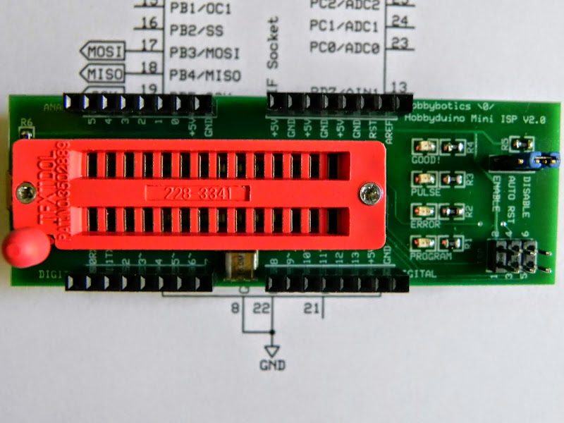
Reference the below schematic and layout file for component locations.


Use It
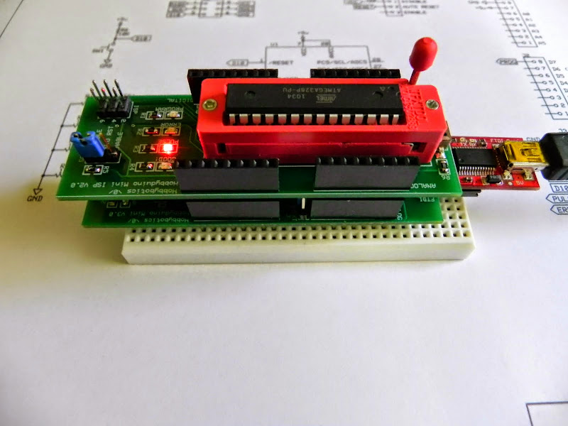
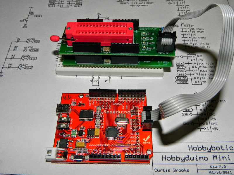
This board can be used in a number of ways with the first being stacked right on top of a Hobbyduino Mini V3.0. Here is what that looks like:

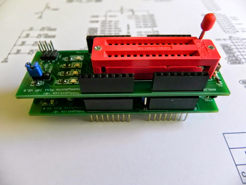
I place this pair onto a small breadboard for stability Like so:

Now, there’s a few things we need to do in order to get the Arduino bootloader onto a blank chip. These are detailed below:
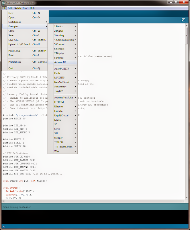
1. We need to upload the ArduinoISP firmware onto the Hobbyduino prior to installing a blank chip onto the ISP shield. Connect aFTDI Basic Breakout or FTDI Basic cable (5V version) to the FTDI header on the Hobbyduino Mini. Make sure the power jumper on the Hobbyduino is set VUSB. This allows the Hobbyduino and ISP shield to get its power from the USB port.
2. Load the ArduinoISP firmware located in — File->Examples->ArduinoISP. It may be necessary to cycle power to the ISP shield after the ArduinoISP firmware has been uploaded. See below:
3. If not already accomplished, attach the ISP shield to the Hobbyduino and install a blank ATMega328. Ensure the lever on the ZIF socket is lowered in order to secure the IC. See below:
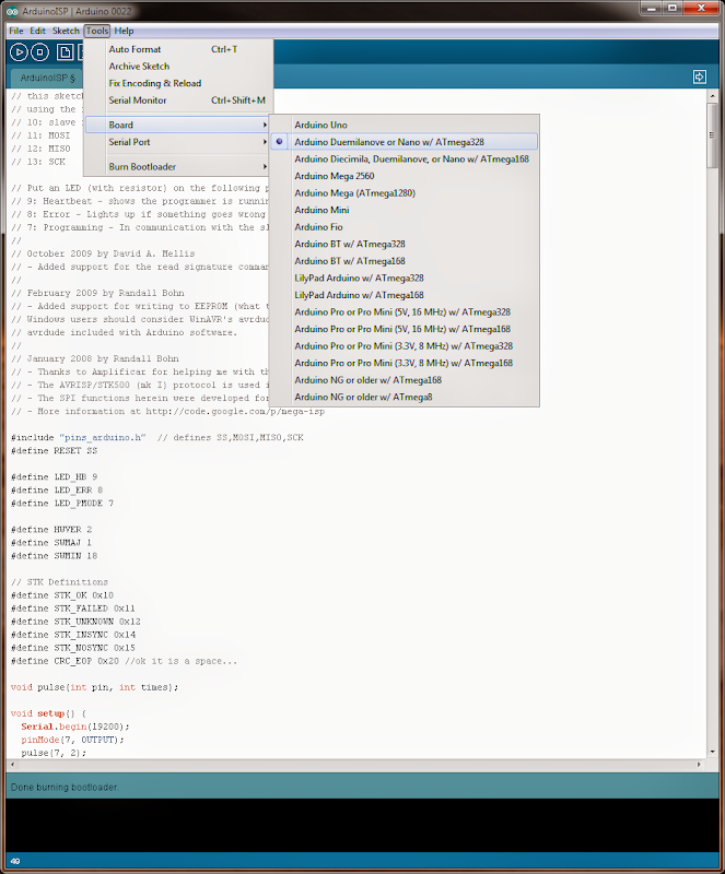
4. Select the target board type from — Tools->Board->Arduino Duemilanove or Nano/ATmega328. See below:
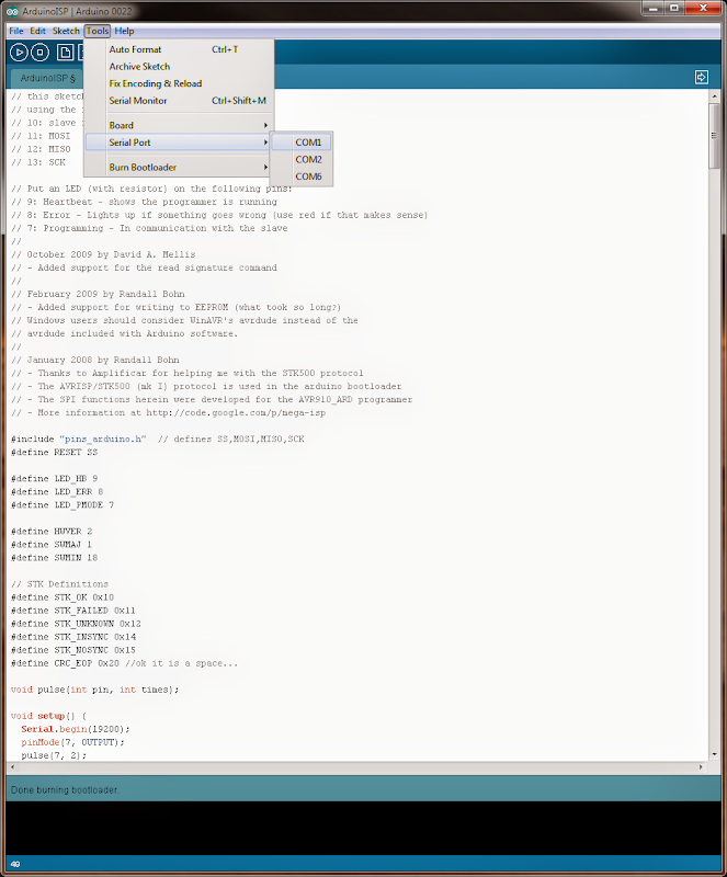
5. Make sure the correct serial port is selected from — Tools->Serial Port. See below (the shown ports may be different on your system).
6. Select Burn Bootloader w/ Arduino as ISP from — Tools->Burn Bootloader–>w/ Arduino as ISP and the process should begin. You’ll see “Done burning bootloader.” at the bottom of the Arduino IDE once the process is complete. See below:

All that is left is to remove your freshly bootloaded IC from the ISP shield and install on an Arduino board of your choice.
Additional Information:
The ‘Pulse’ LED on the ISP shield will blink once the ArduinoISP firmware is installed on the Hobbyduino, the ISP shield is attached, and the Hobbyduino is attached to the USB port.

This is normal as it indicates the ArduinoISP firmware is properly installed.
The ‘Program’ LED will be on while the boot-loader is being programmed onto the IC.
The entire process may take in excess of a minute to complete.
I mentioned above that there are other ways the ISP shield can be used to program the bootloader. Another such method is to use it to burn the bootloader onto external boards that already have a chip installed. This would be accomplished by attaching the external board to the ISP Shield/Hobbyduino combo by way of the 6-pin ISP header. Do not install a chip into the ZIF socket in this setup. See below:
Also, you’ll notice a jumper on the ISP board that allows auto-reset to be enabled or disabled. That jumper will typically need to be set to ‘auto-reset disabled’. I won’t go into why this is the case but, you can read all about it here.
The rest of the setup is as mentioned above.
Related Links
Evil Mad Science – Provided some design inspiration
Hobbyduino Mini Boot-loader ISP Shield Gallery
Disclaimer
This example shows hardware and software used to implement the design. It is recommended the viewer use sound judgment in determining and/or implementing this example for any particular application. This example may include information from 3rd parties and/or information which may require further licensing or otherwise. Additional hardware or software may be required. Hobbybotics or any affiliates does not support or warrant this information for any purpose other than a design example and takes no responsibility for any mishaps (none being implied).
