Introduction
I’m pretty sure the majority of my projects will never be considered “Complete” as I’m always tinkering with the firmware to add or refine features. However, I like to give my projects a finished look which means they will be inside of enclosures or integrated into other devices. It would be nice if I could update the firmware without having to dissect the project to get at the controller. Yes, I could integrate an external USB or serial port accessible with a cable or I could simply adapt the design so that I can use wireless programming. Now, this idea has already been thought up. In fact, I adapted my implementation from this tutorial found on Adafruit (thanks for figuring out the hard part).
The basic idea is to configure one XBee Series 1 module as a transmitter and a second XBee Series 1 module as a receiver (details are below). The serial port will need to be configured to set RTS on close. The RTS pin is used to reset the Arduino bootloader during programming to allow new code to be uploaded. The transmitter will be connected to the serial port through a FTDI Basic 5V breakout board from Sparkfun. The receiver will be connected to the Arduino and toggle the reset pin whenever the DIO3 pin of the XBee detects that the RTS pin of the serial port has been set. More details on how wireless programming works will be explained later.
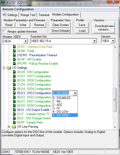
The below table list a quick overview of the settings for the transmitter and receiver modems. These settings are located on the Modem Configuration tab of the X-CTU software.
| Description | Parameter | Transmitter | Receiver |
| PAN ID | ID | User’s Preference (0000 to FFFF). Set to 2359 for this tutorial | User’s Preference (0000 to FFFF). Set to 2359 for this tutorial |
| Interface Data Rate | BD | 57600 | 57600 |
| Packetization Timeout | RO | 10 | 10 |
| DIO3 Configuration | D3 | 3 – DI | 5-DO HIGH |
| DIO Change Detect | IC | FF | Not Set |
| I/O Output Enable | IU | Not Set | 0 – DISABLED |
| I/O Input Address | IA | Not Set | FFFF |
The goal of this tutorial is to explain how to use two of the Hobbyduino XBee Plugs to wireless program an Arduino or Arduino clone (a Hobbyduino Mini for this tutorial). First, we’ll start off by outlining the necessary parts. Second, we’ll cover how to configure each XBee and XBee plug as a transmitter and receiver. Third, we’ll setup the serial port for proper communication. Fourth, we’ll upload a demo sketch to the Arduino and pray that the fruits of our labor has paid off. Lastly, we’ll go over the finer details of how the wireless programming works. Let’s go over the necessary parts before we get into the details of how to configure the XBee modules and plugs for wireless programming.
Parts List
This tutorial was written to support using the Hobbyduino Mini XBee Plug to wireless program a Hobbyduino Mini V3 and will not work with other XBee Adapter kits and/or Arduino’s without consideration of the differences in configuration. In addition, XBee Series 1 modules have different configuration settings than Series 2 modules. As such, XBee Series 2 modules can not be used for this tutorial.
(2) XBee Series 1 modules. You can get them from Adafruit or Sparkfun.
(2) Hobbyduino Mini XBee Plugs. Checkout the project page for details.
(1) FTDI Basic breakout board. Available from Sparkfun.
(1) Hobbyduino Mini V3 or other Arduino compatible board. Checkout the project page for details.
(1) 5V to 12V power source for the Arduino (I use a 9V battery for this tutorial).
X-CTU software. Download from Digi.
Arduino IDE. Download here.
Step 1: Configure the Transmitter
One of the Hobbyduino XBee Plugs will be paired with an XBee configured as the transmitter. This XBee will be connected to the computer via an FTDI Basic breakout board.
1. Install one of the XBee modules onto the associated header of the XBee adapter.
2. Attach the FTDI Basic onto the associated header of the XBee Adapter.
3. Connect the USB cable to the FTDI Basic and computer. The power LED should illuminate.
4. Launch the X-CTU software.
5. Select the port that is connected to the FTDI Basic and press the “Test / Query” button to ensure proper communication can be established with the XBee modem. The Modem type, firmware version and communication status “OK” should be displayed. The default 9600 baud rate should work unless you have previously changed the communication rate in the XBee configuration settings.
6. Go to the Modem Configuration tab and press the “Read” button in the Modem Parameters and Firmware section. The modem parameters should be displayed in the status window.
7. The default PAN ID should be the default hexadecimal value (3332). This value should be changed to a number that will only be used by these two XBee modems. I changed the value to (2359) for this tutorial.
8. Set the baud rate to 57600.
9. Set the Packetization Timeout to at least 10. This value is what determines how long to wait before sending data over the serial port.
10. Set pin D3 to be a digital input (3 – DI).
11. Set the DIO Change Detect to (FF) so the modem can detect changes on pin D3 and press the “Write” button in the Modem Parameters and Firmware section to write the parameters to the modem. “Write Parameters…Complete” should be displayed in the status window.
12. Press the “Read” button in the Modem Parameters and Firmware section to verify the settings are correct.
13. Configure the RTS to IO3 jumper on the XBee adapter. This will tie the status of D3 to the status of the RTS pin. The RTS pin is used to reset the Arduino.
Step 2: Configure the Receiver
One of the Hobbyduino XBee Plugs will be paired with an XBee configured as the Receiver. This XBee Plug will be attached to the Hobbyduino Mini V3 and reset the Arduino when it detects changes on pin D3 (IO3).
1. Repeat steps 1 through 9 above to configure the PAN ID, baud rate and Packetization Timeout.
2. Set pin D3 to be a digital output (5 – DO HIGH).
3. Set the I/O Output Enable to disabled (0 – DISABLED).
4. Set the I/O Line Passing Input Address to (FFFF).
5. Press the “Write” button in the Modem Parameters and Firmware section to write the parameters to the modem. “Write Parameters…Complete” should be displayed in the status window.
6. Press the “Read” button in the Modem Parameters and Firmware section to verify the settings are correct.
7. Remove the RTS to IO3 jumper on the XBee adapter.
Step 3: Configure the Serial Port
The serial port that the FTDI breakout is connected to needs to be configured so that the RTS pin will reset the Arduino.
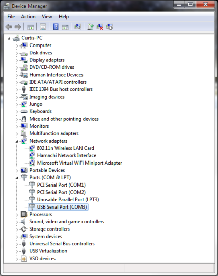
1. Open the Device Manager and select the serial port that the FTDI breakout is connected to.
2. Right-click on the port and select Properties.
3. Click on the Port Settings tab and click the “Advanced…” button. Click on the “Set RTS On Close” check box to select it. Click the “OK” button to confirm the selection.
That completes the setup for the transmitter and receiver nodes. Now, let’s test the operation.
Step 4: Load a Test Application
We have completed the configuration for the transmitter and receiver and setup the serial port so that it will be able to reset the Arduino. In this section, we will write some test code and hopefully get it to load into the Hobbyduino Mini V3 over a wireless connection.
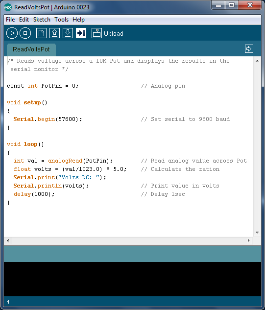
1. Run the Arduino IDE and copy-n-paste or download the below code.
/* Reads voltage across a 10K Pot and displays the results in the
 serial monitor */

const int PotPin = 0;                  // Analog pin

void setup()
{
  Serial.begin(57600);                 // Set serial to 9600 baud
}

void loop()
{
  int val = analogRead(PotPin);        // Read analog value across Pot
  float volts = (val/1023.0) * 5.0;    // Calculate the ration
  Serial.print("Volts DC: ");
  Serial.println(volts);               // Print value in volts
  delay(1000);                         // Delay 1sec
}
2. If not already accomplished, plug the XBee adapter that is configured as the receiver onto the Hobbyduino Mini V3 and connect a power source. Connect the XBee adapter configured as the transmitter into the USB port on the computer.
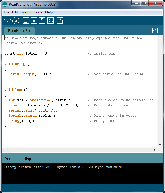
3. Press the “Upload” button in the Arduino IDE and, if all goes well, the above code will successfully load into the Hobbyduino Mini V3.
Here is the output from the above sketch. The circuit reads the voltage across a 10K potentiometer and sends the results to the serial monitor. The above sketch matches the 57600 baudrate that the XBee modems were set to. Ensure the baudrate in the serial monitor matches.
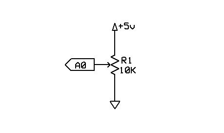
Here is a simplified schematic on how to connect the potentiometer to the Hobbyduino. Basically, the wiper (center pin) of the potentiometer is connected to analog pin A0 of the Hobbyduino. The other two legs of the potentiometer connects to 5V and GND, respectively.
We have completed the configuration for the transmitter and receiver, setup the serial port and uploaded a test sketch to the Hobbyduino over a wireless connection. Next, we will cover the details of how the wireless scheme works.


