Projects – Hobbybotics Reflow Controller Quad V1.0

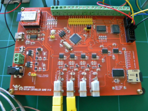
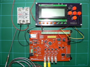
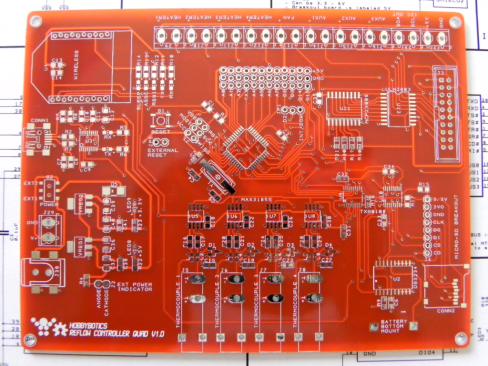
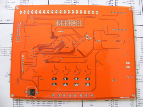
Here’s a quick update to the new reflow controller project I introduced earlier.  I have fully populated one of the prototype boards and began to write test sketches to ensure it functions properly.  The project is moving a little slower right now as I am in the process of closing on a new house and that has been taking up a lot of my time.

2013-03-06 02.44.49_1024x768 2013-03-06 02.44.40_1024x768 2013-03-06 02.44.15_1024x768

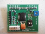
The last picture shows an early prototype for the LCD/Button interface for the controller.  I am in the process of redesigning the LCD/Button interface to use a 4-way rotary navigation switch with a center select button.  I borrowed this idea from the Viki LCD project over on Kick Starter.  I’ll post more updates in the coming weeks.

Projects – Hobbybotics Reflow Controller Quad V1.0

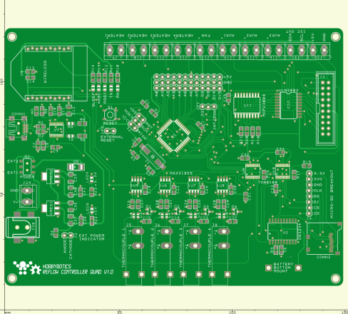
I’ve been working on a redesign of the original reflow controller.  Here are the features for the new board:

  1. Four MAX31855 Type-K Thermocouple interfaces
  2. DS3234 Real Time Clock with battery backup
  3. FT231x USB
  4. XBee or Bluetooth Wireless
  5. MCP23008 I/O Expanders for 2-wire expanded communication
  6. ULN2803 Darlington buffered output relay/SSR control
  7. Internal or external micro SD interface
  8. External LCD I2C interface/input
  9. ATMega 1284P TQFP AVR with Arduino bootloader
  10. 16 MHz Crystal

Take a look at the new board:

2013-02-19 01.32.48_1024x768

2013-02-19 01.36.35_1024x768

download

 I’ll post more on this project in the coming days.  I’ll be offering this project as a full kit for those who are interested.

Projects – Hobbybotics Serial LCD Controller V3.0

p80900101Some of the projects I design make use of character displays. The Liquid Crystal Displays (LCD) I typically use are based on the Hitachi HD44780 LCD command set. Most HD44780 compatible LCDs use a standard 16 contact interface and are known as parallel devices. This project presents a design that allows the LCD to be controlled by a single serial pin from a microcontroller or a serial connection on a computer. Check out the project here

Software – codebender: A Web Platform for Hackers, Makers and Artists

I am now a supporter of the crowd-funded open-source project known as codebender.  Codebender is a cloud-based Arduino IDE that provides the capability to edit, compile and upload your code to an Arduino from a web browser.

The cloud based IDE implements clang which is a compiler that provides descriptive warnings, fast compile times, low memory usage and compatibility with GCC.  In addition, codebender contains built-in highlighting, Arduino documentation, support for libraries and a serial monitor.


Pledge $150 and you will receive exclusive access while the project is still in development, a monthly newsletter and an Arduino Ethernet preloaded with codebender’s (upcoming) TFTP bootloader.  The bootloader will allow any Internet connected Arduino to be programmed through a web browser locally or away from home.

All of the sources for codebender can be found on the associated Github page.

Tools – MakerBot Replicator

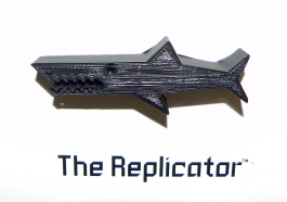
I wanted to get into 3D printing so that I can start working on some physical interfaces for my design circuits. Traditional 3D printers are way out my price range but, along comes the RepRap movement and with it an army of 3D off-shoot printers.  Now, 3D printing is within reach of the hobbyist.  I decided to purchase a MakerBot Replicator because the company is pretty well known for quality products and the Replicator has a dual extruder.

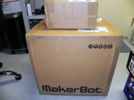
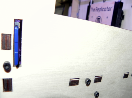
MakerBot fully builds and tests each Replicator before shipping and packages each machine very well.
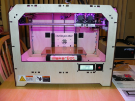
  

I followed the instructions from the MakerBot setup videos and manual without any issues.
The Replicator has an SD slot built in so that you can save designs to a card and run them straight from the machine.  I selected one of the sample designs already loaded onto the SD card for my first print.
  

Another option is to load designs into the ReplicatorG software, connect a USB cable and print from the PC or MAC.

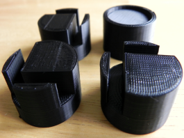
Here is a screenshot of my next print loaded into ReplicatorG along with the results:


These are replacement feet for the Replicator as the stock set is cut rubber tubing which does not stay on very well. The design can be found here on Thingiverse.

I need to go through some more tutorials before I feel comfortable enough to create and print my own designs (there is a slight learning curve to the Replicator).

Onward I march so that I can finish up my Probotix FireBall V90 CNC build.

Tools – FireBall V90 CNC Build – Day 5

On day 5 I got all of the limit switches mounted to the machine.  I spent some time trying to figure out where and how I wanted to mount the switches.  I also needed to find an easy way to actuate them when the machine reaches a limit.  I scrounged around in my junk parts bin and came up with some pretty neat methods on how to actuate the switches at each limit.  The main requirements of my chosen scheme is to make it look neat and keep it functional.  Go here to read about the ongoing build and take a look at some pictures along the way.

Tools – PCB Shear

I typically send my circuit boards to ITead Studio to have them produced since it is cheaper than ordering them from US companies.  International orders can take a long time to ship..usually around 3 weeks.  This can become painful if I find a mistake in my design and have to re-order boards.  This is why I occasionally bite the bullet and have them made locally.  One of the techniques I use to minimize the cost is to place multiple circuit designs onto a single PCB.  The problem with doing it this way is there are no snap off tabs between the circuits like you would receive from a panel.  There are numerous methods that a hobbyist can use to separate the circuits such as a Dremel or saw.   I want a clean cut so using a Dremel tool is out of the question.  Also, the material the boards are made of is toxic thus, it is not recommended you cut them out on a table, band saw, etc.  A PCB shear will give you a clean straight edge and makes short work of cutting out the individual circuits.  I have seen some individuals using a heavy duty paper shear but, I wanted something that was more accurate with a longer lasting blade.  The shear is available from T-Tech.  The cost is a tad on the high side but, it is better to spend now and save later IMHO.

Here is a picture of the PCB Shear:

Image

Project – Internet Enabled Multi-zone Thermostat (DesignSpark Challenge Entry)

I’m currently working on documenting this project but, here is a link to my entry for the DesignSpark Challenge. The competition has already been decided and my entry garnered an honorable mention award! This was the first competition that I entered and to win an honorable mention out of over 1000 entrants means a lot to me. I also won a Community Choice Award during the competition for the most popular project. I have to say this was a difficult competition as there was a lot of requirements. For instance, I had to learn how to use DesignSpark PCB as it was required to produce an extension board for the ChipKit Max32. I had to learn the ins and outs of the Max32 as it is/was not entirely compatible with all of the Arduino libraries. This meant some modifications to libaries in order to make them compatible with the Max32. Lastly, there was a long wait for the PCBs to be shipped from China which meant any mistakes in the board files meant lost development time (I made a few mistakes). Time management was definitely crucial in this competition and I ran all the way until the last few minutes for project completion trying to get everything together. A few mistakes kept me from adding all of the software features that I had intended but, I have pretty much completed them since the competition. Check out my entry here and be on the look out for full documentation on my blog to include some extension projects (There’s a lot of goodies in this design that can be carried over into other projects).

Tutorials – Eagle Tutorials from Around the Web

I have used many schematic/PCB capture applications and I find that Cadsoft Eagle seems to be the standard for hobbyists.  As such, there are some peculiar features that takes some getting use to.  For instance, the user interface does not function like many point-n-click applications.  You can Google eagle tutorials and find plenty.


Below are some of my favorites: